Cluster Control Plane Assembly
Table of Contents
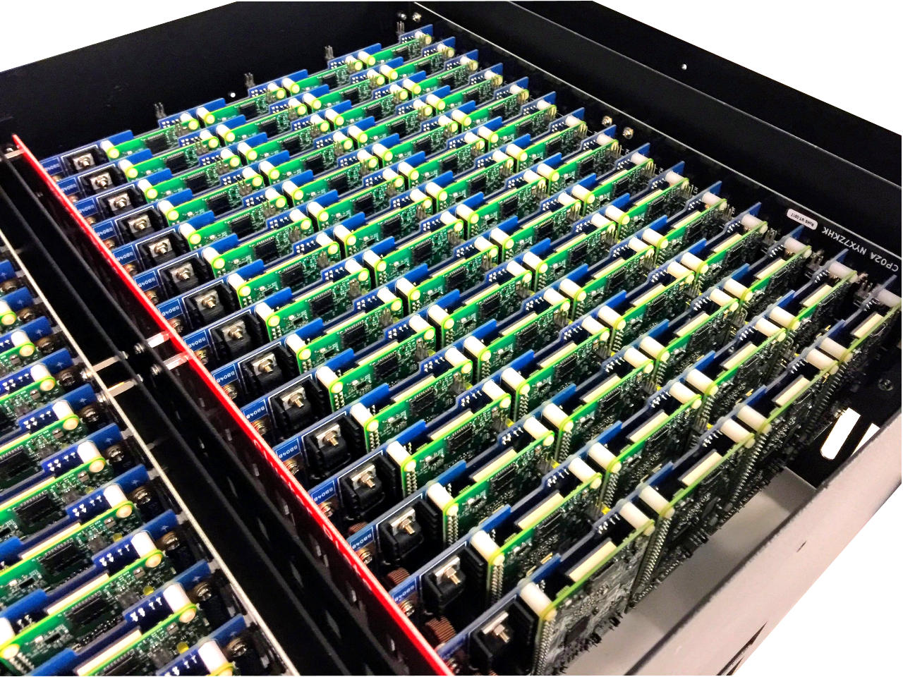
1 Remove Power shunts
Remove all the red power shunts. As you proceed, check each set of pins for any that are bent or mis-aligned. Fix any problems before attempting to install BitBars.
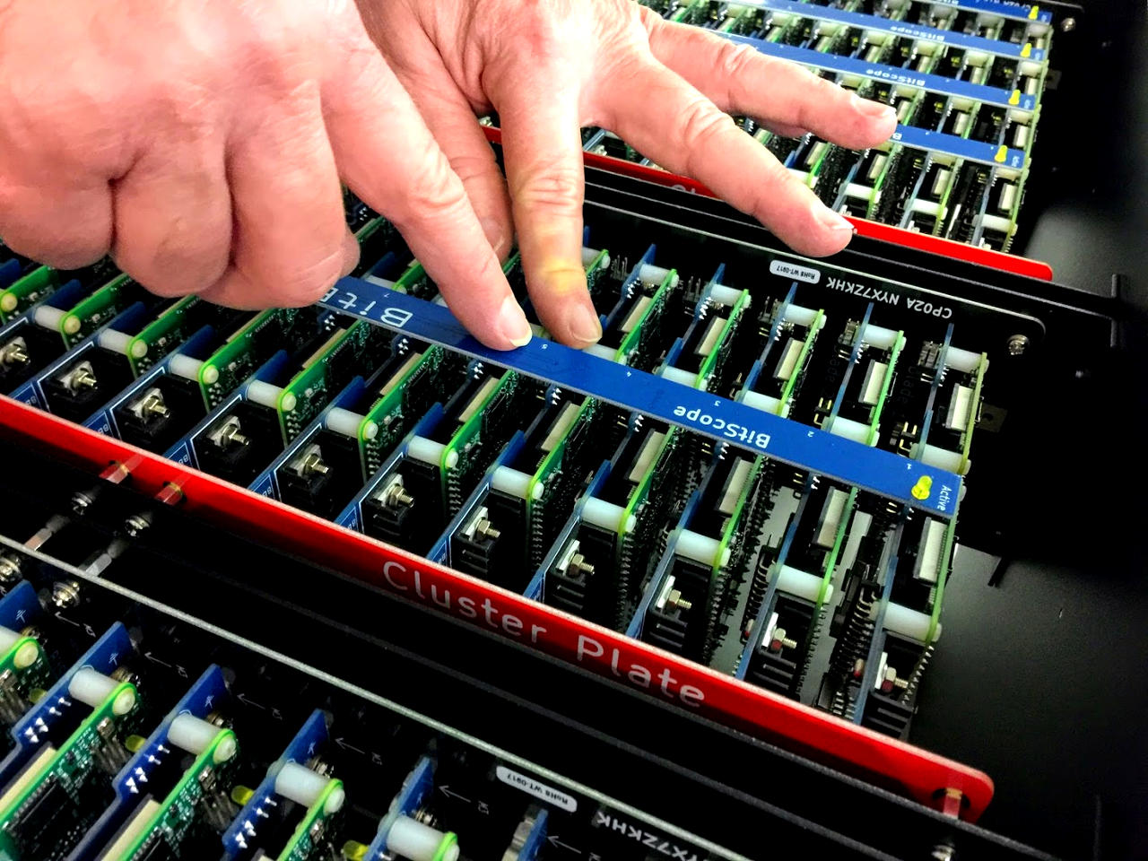
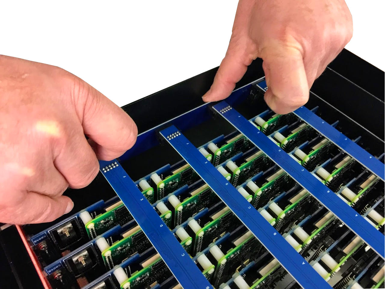
2 Install BitBar Power Control Strips
Work with the LED end of the BitBar away from you. Place the BitBar over the pins, and starting from the LED end, let the pins find the socket holes.
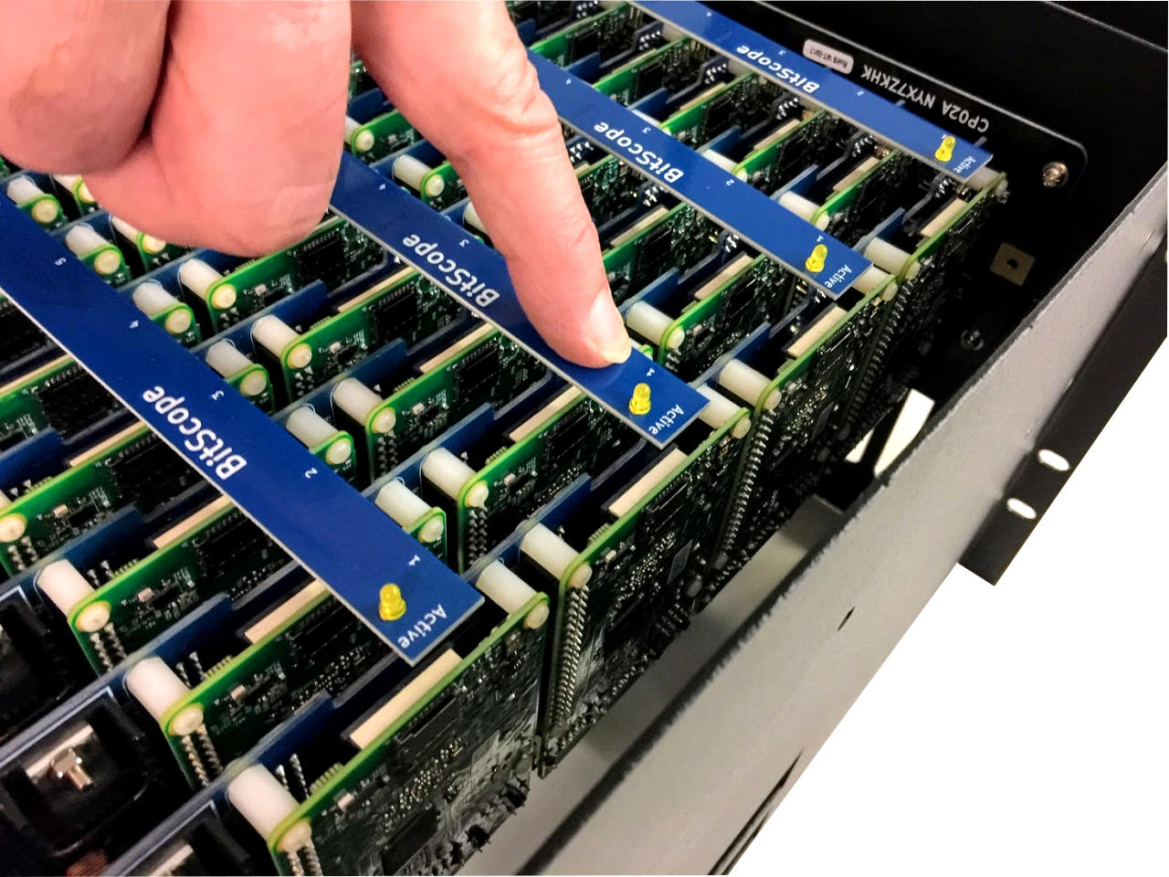
If the pins catch, you should gently flex the Blade pcb so the pins find the socket easily.
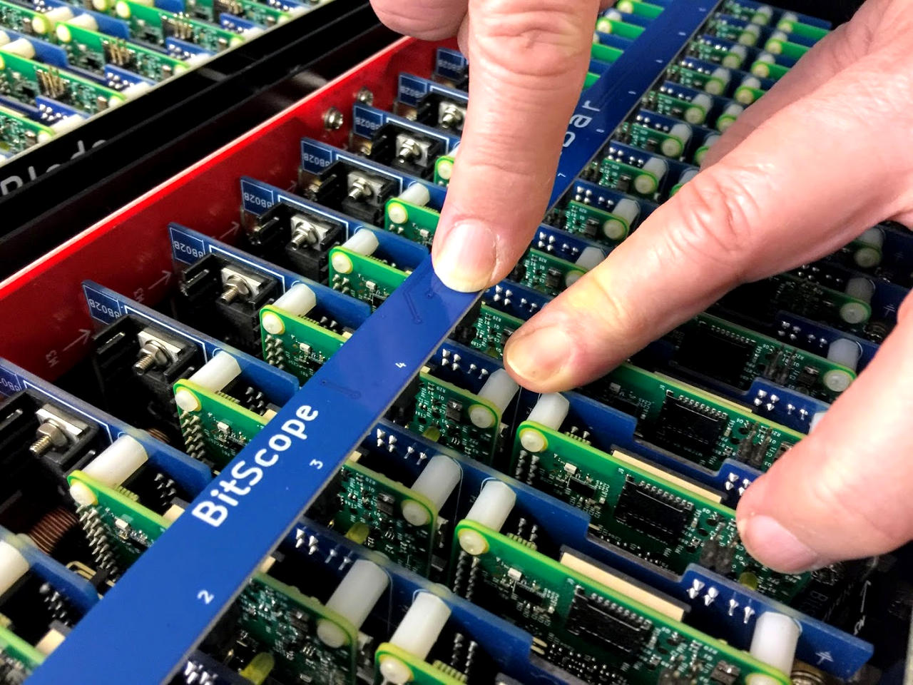
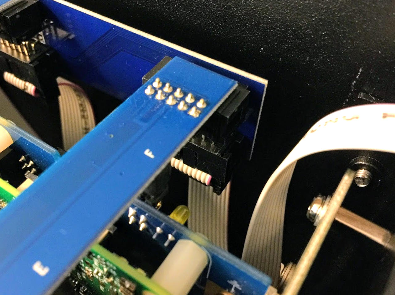
Once all the pins are sitting in the socket entries, start from the LED end and gently ease the BitBar down so all the sockets are flush. Pay attention as you push the BitBar down. If there is any resistance check that the pins are correctly aligned before proceeding.
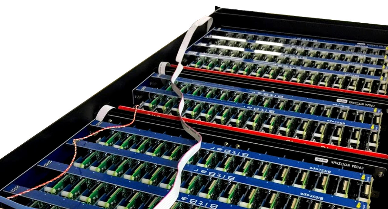
3 Install Bridge Boards
With all the BitBars correctly seated, next attach the Bridge PCBs to the 10 way socket header on each BitBar
Attach the short 10 way IDC cables between the Bridge PCBs in adjacent cluster packs.
Attach the long 10 Way IDC to the Quattro Bridge IN port at the very front of the module.
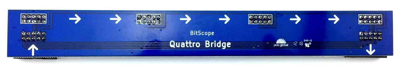
The wiring of the BitBars sets the geographical address for the nodes. To ensure the front row of nodes is as the lowest address the cable must be connected to the front cluster pack in the module. The control flow from the Cluster Hub should follow the arrows on the Bridge PCBs, shown as either IN or OUT (in this case for Quattro, Duo is similar).
4 Install HUB Power Controller Board
Remove the rear panel of the module to access the wiring loom and Hub.
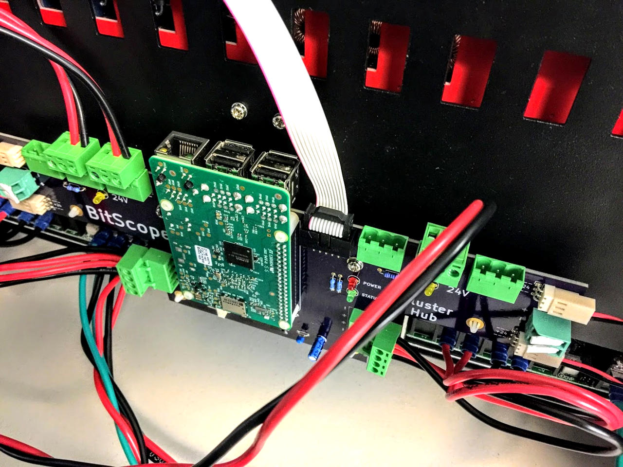
The new Active Cluster Hub is a direct replacement for the old one, with some minor mounting changes. The lever connectors for the front panel LEDs have been moved to between the FAN sockets, otherwise all connectors are in the same place. Remove the outer metal standoffs. Use the four adhesive PCB standoffs supplied in lieu. The inner standoffs are unchanged.
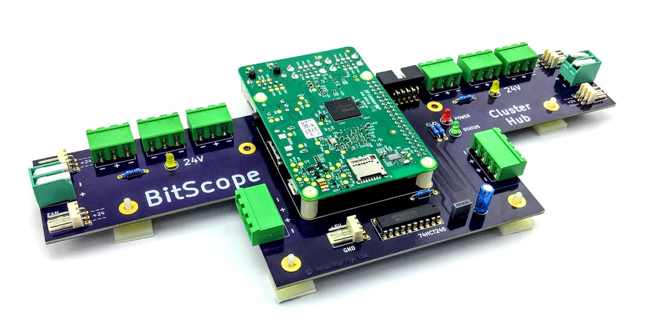
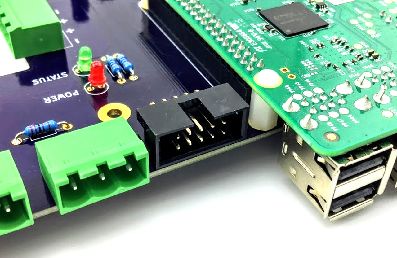
The Active Cluster Hub now has a 10 Way box header which accepts the long IDC cable to control the BitBars
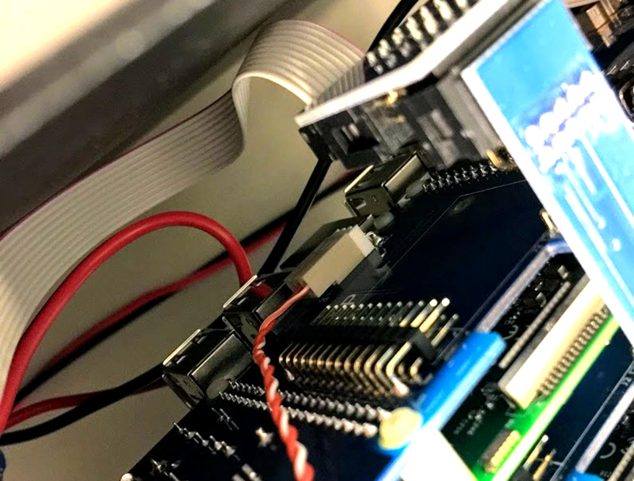
The RPi on the Active Cluster Hub is powered by +5 volts from a Duo Blade. The 3 pin header is at the bottom left.
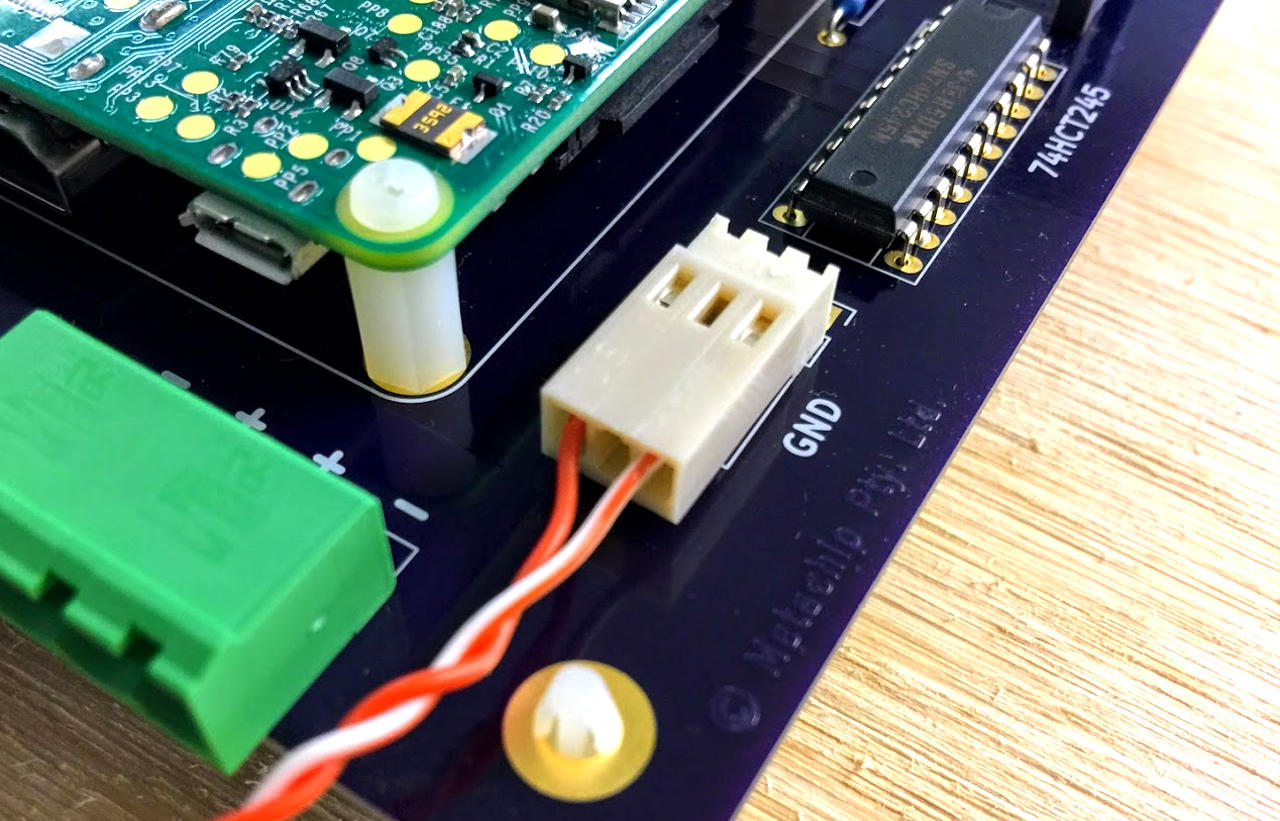
Attach the other end of this twisted cable to the nearest Duo Blade IMPORTANT: This cable is not reversible! The Cluster Hub end connects to the outer pins, the Blade end is +5 on the center pin. It's important to connect to power on a Duo Blade in the cluster (not a Quattro Blade).
The Raspberry Pi on Active Cluster Hub needs to be connected to the client computer. The HUB runs its own operating system, normally bootstrapped from SD card. However, it may be connected to the network and PXE booted as well. When connected to the BitBars all other nodes in the cluster will detault to POWER OFF when the cluster is powered. This means that until the Active Cluster Hub is powered and bootstrapped and running, the cluster itself will remain quiecent. Each BitBar has a Yellow LED connected to the 16th bit of its control register. The software driver will normally turn all these LEDs ON when initialisation is complete. To confirm the control plane is physically connected to each node, disconnect the ribbon cable from the Cluster Hub. In this case when the cluster is powered on, the default state for all nodes is also on (just as if the control plane was not installed).
5 Optional (Recommended) Step
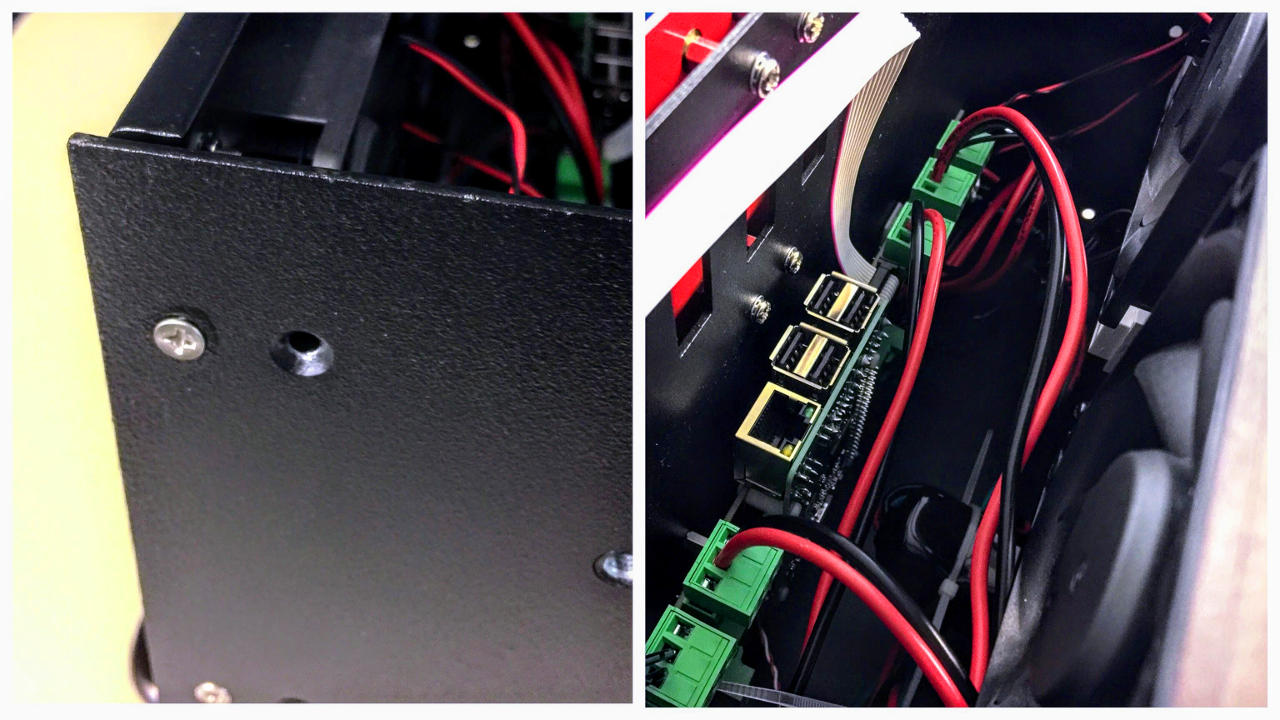
If you find the rear of the power socket protudes too far back to allow a comfortable space between the Cluster Hub and the rear panel, we recommend you drill a set of mounting hole 18mm aft of the originals to the rear plate mounts slightly further back as shown here. This will allow enough space to accommodate the Cluster Hub even if the rear power socket used is the larger one.
BitScope Cluster Module Control Plane Assembly and Installation, Document Version QKSD4SAT/02
6 References
| Permalink | https://docs.bitscope.com/QKSD4SAT |
|---|---|
| Document ID | QKSD4SAT 02 |
| Copyright © | 2018-2019 BitScope Designs |
| Revision | Update |
| 02 | updated |
| 01 | created |