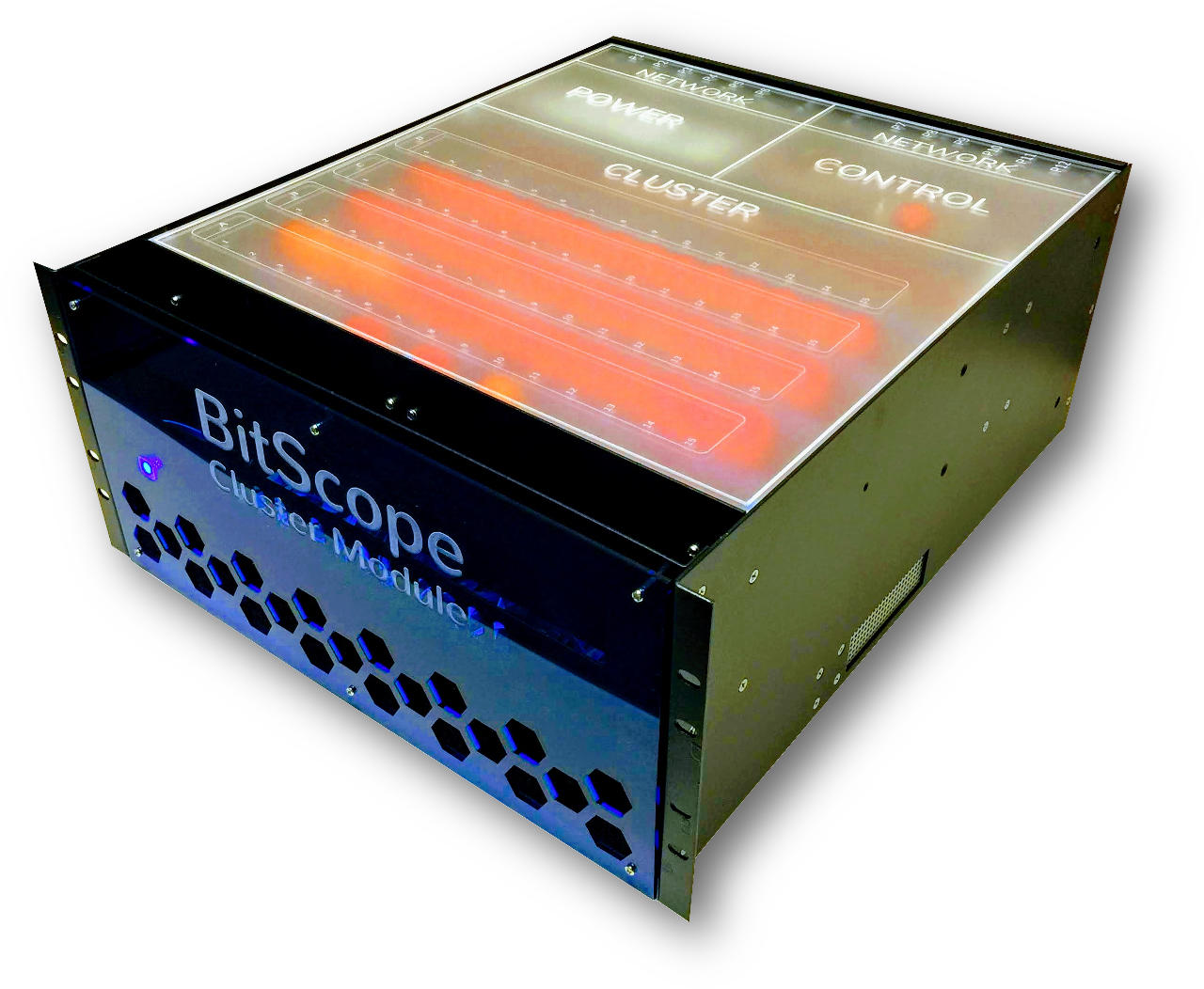
BitScope Cluster Module Guide
Table of Contents
PRODUCT INFORMATION UPDATE
This document describes BitScope Cluster Module 48. It is an existing product undergoing a design revision enabling it to accomodate Raspberry Pi 4 Model B 8G with Cluster Blade. The changes are backward compatible in terms of physical form-factor and cooling sub-systems. However the control plane and power delivery are being significantly upgraded to enable Raspberry Pi to be used for heavy workloads and to enable console access to each node.
Some information in this document will therefore be updated as this work proceeds.
This document describes how to unpack, configure, install and use your Cluster Module.
Unpacking
BitScope Cluster modules are packed for shipping in custom designed packing crates. The crates are well padded and designed as "snug-fit" around the cluster module to ensure safe transit. Refer to this image when unpacking a module (notes these images are for large modules, small ones are similar):
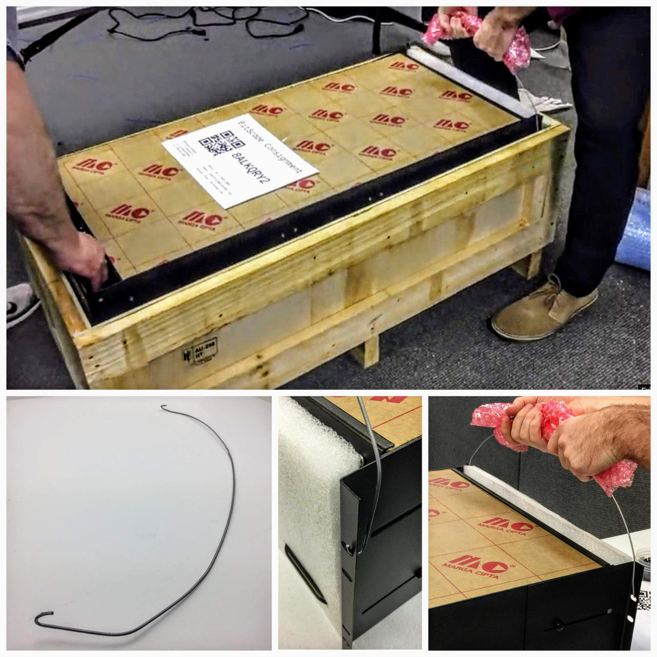
This requires two people to lift the module out of its crate.
To remove the module:
Once the module is removed from the crate the use of the tool is optional. However, it is important that the module is not dropped or otherwise exposed to external shock so caution is required with lifting and/or relocating it.
Component Check
During transit the cluster may be been subject to vibration. The packing is designed to accomodate for this. However, it may be that some of the Micro SD cards work loose. If there are some missing they will likely be located at the floor of the cluster module. If any become lost, simply may a copy from an existing one to a new one. If you have none, contact mailto:support@bitscope.com
Configuration
The cluster module has an internal 52 port network switch.
The first 48 ports connect to 48 LAN cluster nodes. The other 2 ports are available to connect to external networks and/or inter-connect the subnets inside the cluster. When first commissioning the cluster module it is necessary to interconnect the switch to the cluster control manager.
The network switch and the cluster manager must be connected in this way to be able to run the bootstrap self test sequence. If not connected the nodes will not boot.
To do this connect the supplied pigtail patch cable as follows:
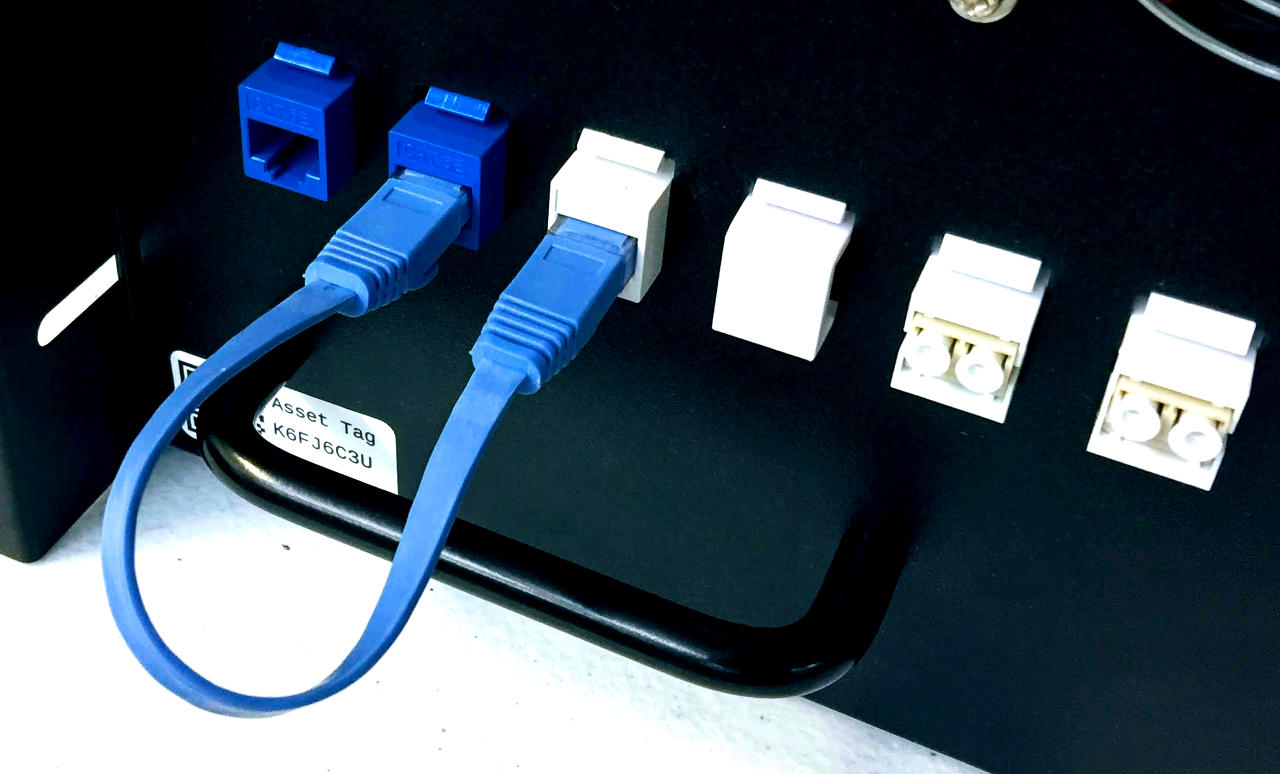
This connects the cluster hub (white keystone) to one of the two uplink connections (blue keystone). The other blude keystone allows connection to the external LAN. There are two fibre connections (white keystones on the right). These are not provisioned in this module. However they may be used to connect fibre links instead of one or both copper links, if required.
The cluster manager bootstraps from a Micro SD Card located as shown:
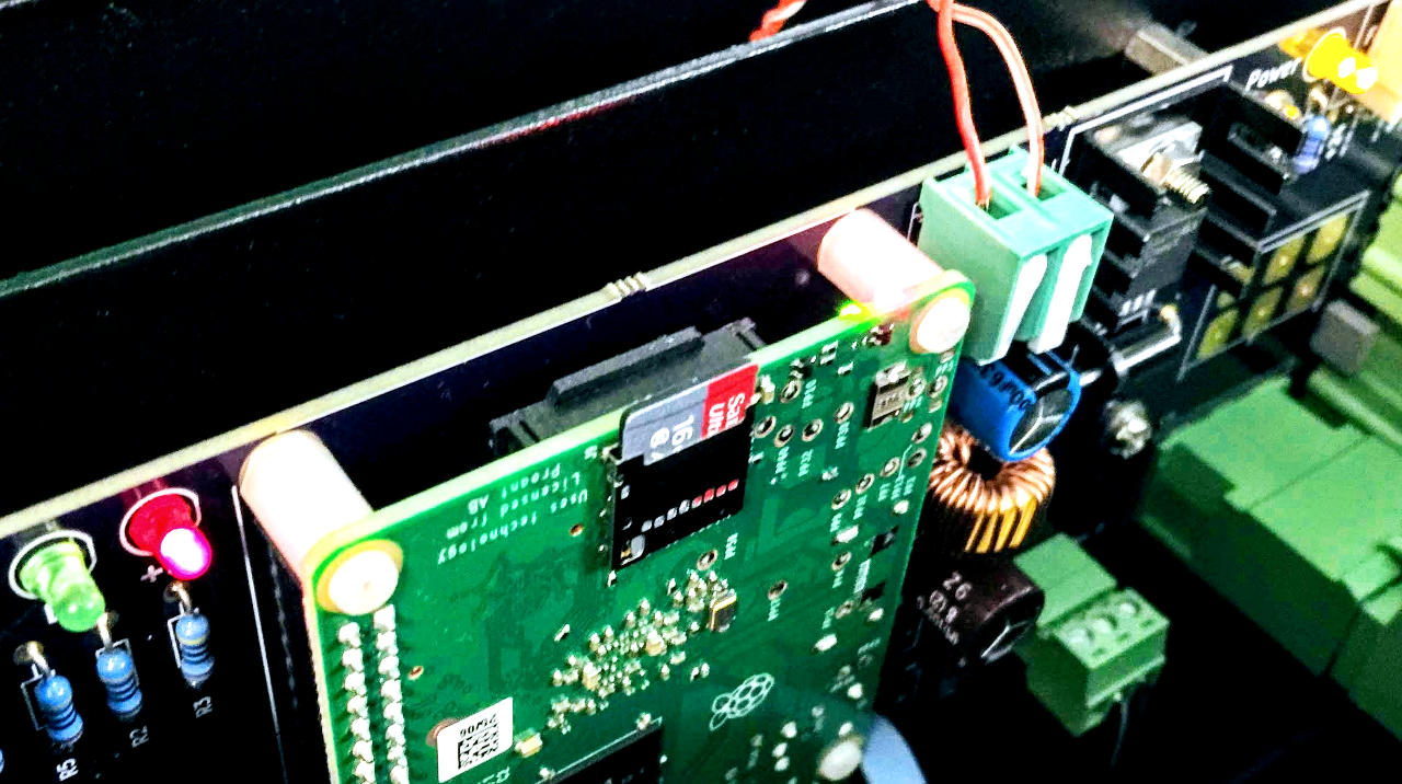
Be sure this card is in place before powering the cluster module for the first time.
The cluster manager requires this image to be able to control the cluster. In addition to managing the control plane hardware, it provides DHCP/DNS and TFTP/PXE boot services to the module.
Asset Tags
The cluster module is identified by its asset tag:
| SKU | MODEL | TAG/ID | NOTES |
|---|---|---|---|
| CM48A | QA6QDEDP | NMEBW9HT | cluster module 60 |
The TAG/ID appears on stickers applied to exterior and interior of the module. Ensure these tags are not removed or relocated. They are used to identify the module for service and support enquiries.
Power On
The cluster has three main components that must power on to bootstrap correctly:
Power is applied to all three immediately but the control plane (re)boots the nodes when the switch has completed its bootstrap sequence. The cluster manager controls the sequence. It is located at the rear of the module:
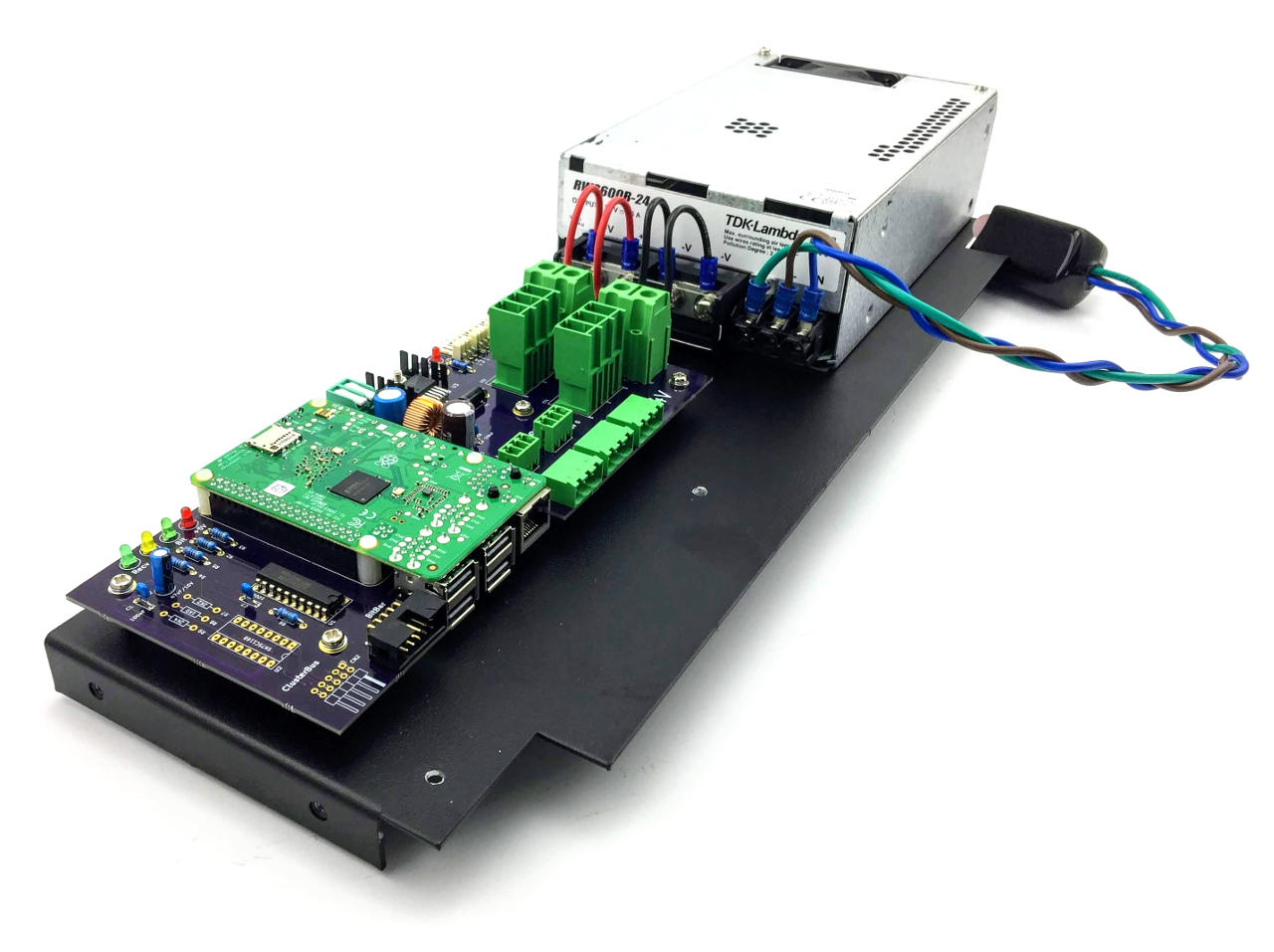
It is required to power up the cluster and manage use the control plane. The control plane drivers, cluster manager and self-test software is all located on the USB thumbdrive and/or the Micro SD card plugged into into the Raspberry Pi on the hub. The image uses Raspbian Lite and we recommend it be backed up before use.
The cluster manager is pre-configured to perform a power-on self test. The test confirms correct operation of the cluster control plane and the connected nodes in the cluster. This software runs on the cluster control hub.
Bootstrap Overview
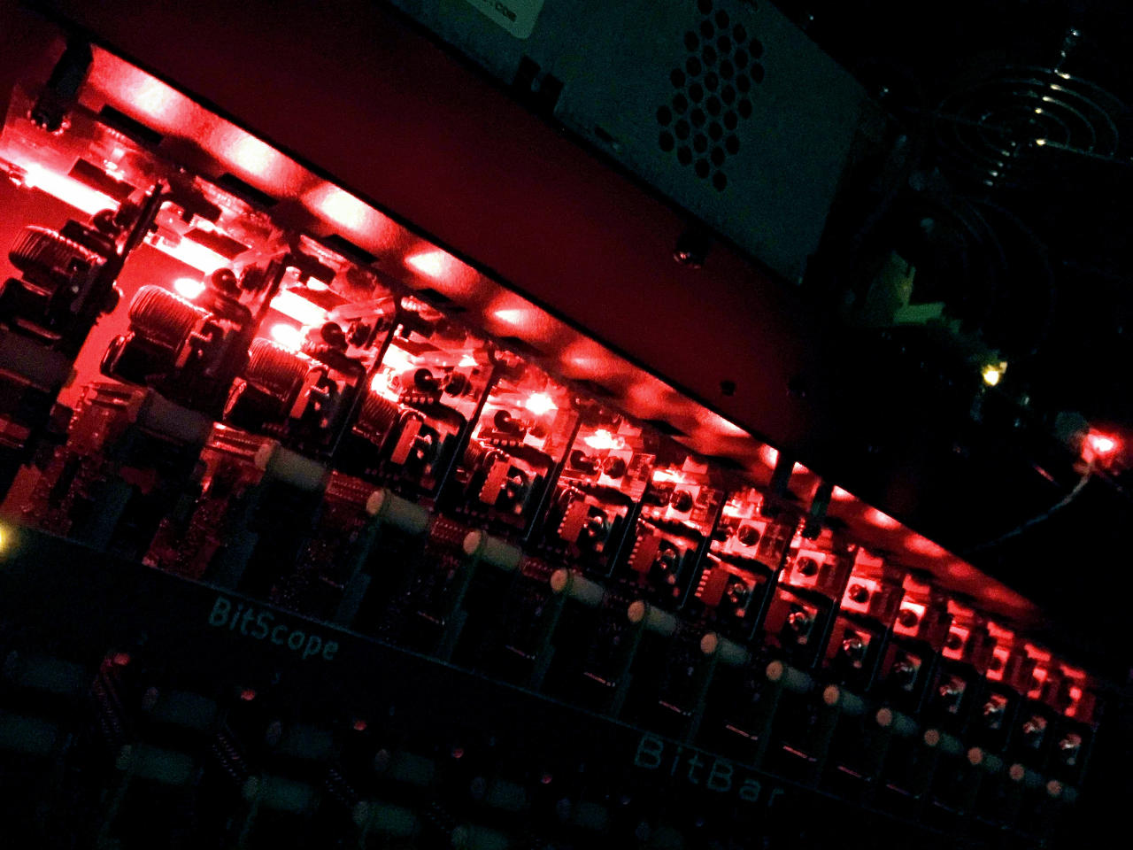
When the cluster is first powered on, all blade power lights (at the end of each blade) illuminate immediately. Underneath a mix of green and red light from the network ports may also be visible.
Next all the nodes with Raspberry Pi 3B or 3B+ installed and connected to the network will illuminate. Nodes that have Raspberry Pi Zero installed will not illuminate. The cluster will then turn off nodes off and progressively bootstrap to the client image over a period of several minutes.
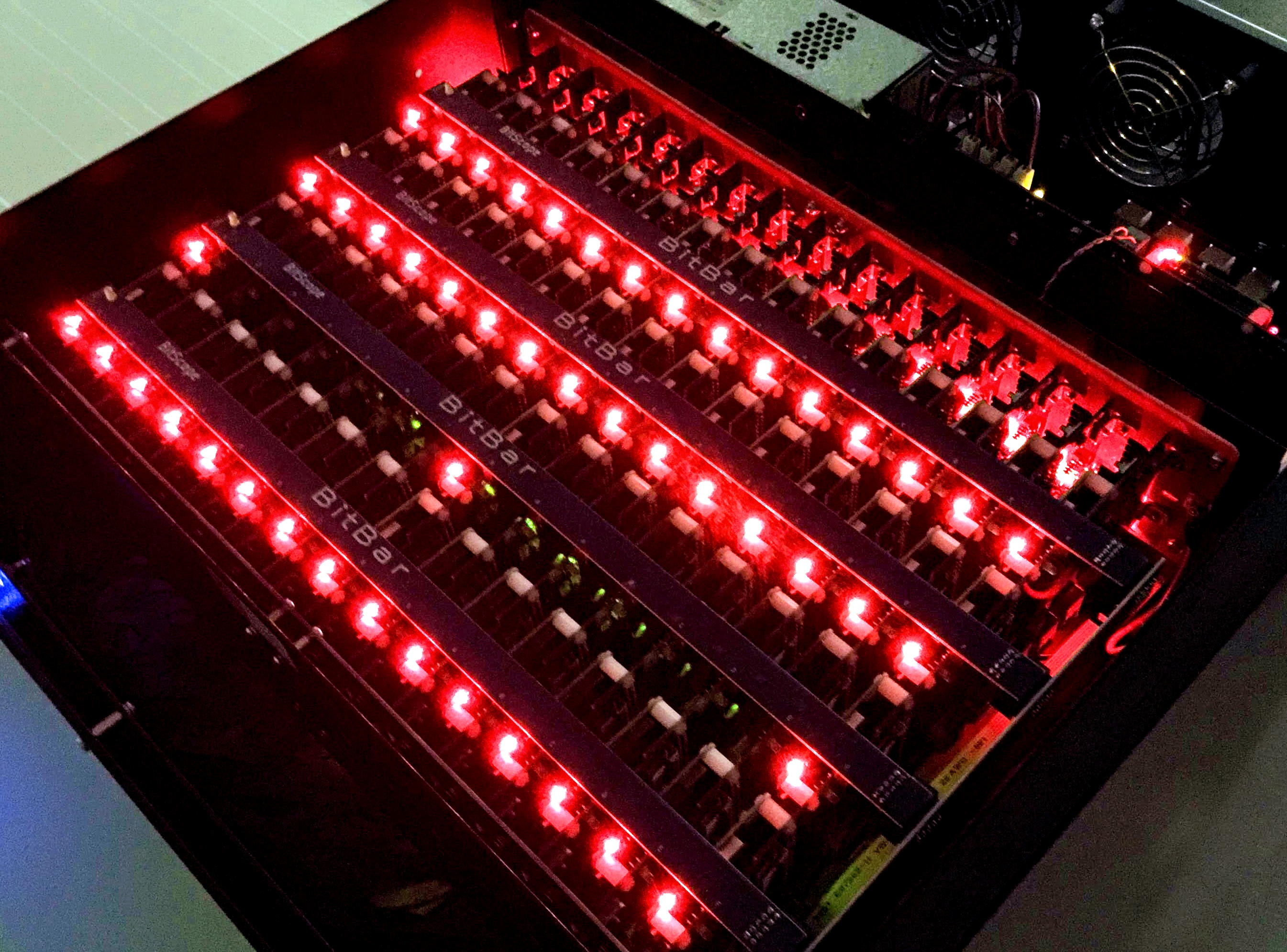
First the control plane lights will appear when the controller is boostrapped. After about 2 minutes of self tests and control plane configuration:
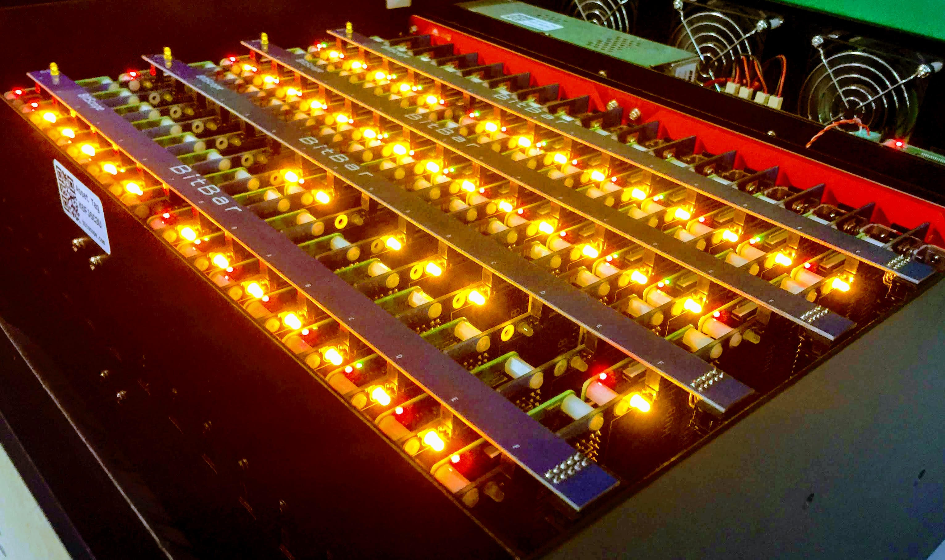
The cluster nodes will run the default image which flashes the node bay lights. The Raspberry Pi 3B and 3B+ nodes illuminate for 900ms and briefly turn off for 100ms. The Raspberry Pi Zero W nodes (if installed) do the the inverse (900ms off followed by 100ms on).
Bootstrap Detail
In detail, the boot sequence is as follows:
Twelve nodes, in the second row, will not illuminate. This is normal. They are the Raspberry Pi Zero W and they do not have power and activity LEDS. They are not connected to the LAN either. Instead they boot from SD cards and they can connect via WiFi. A WiFi hub is required to connect to them. The cluster manager can be configured as the WiFi HUB but this is not the case by default. The Pi Zero W nodes are looking for this WiFi configuration:
country=US
ctrl_interface=DIR=/var/run/wpa_supplicant GROUP=netdev
update_config=1
network={
    ssid="client"
    psk="secret"
    priority=1
}
A WiFi AP with this configurtion must be provided or the file
/etc/wpa_supplicant/wpa_supplicant.conf
on the SD card in each Pi Zero W node must be changed to suit the local WiFI AP configuration.
Node Map
The 60 nodes in each module are geographically identified by their control plane ID.
The control plane numbers nodes from 1 to 60. When a cluster module boots with the default image, the control plane enables all nodes in sequential order. When viewed from the right of the module, node 1 is at the top-left of the module with node 2 below it down the first control plane bus (BitBar), followed by the second bus up to the tenth at the rear of the module.
The MAC addresses table for the 60 nodes in each cluster are:
| ID | NMEBW9HT 01 |
|---|---|
| 1 | b8:27:eb:XX:XX:XX |
| 2 | b8:27:eb:XX:XX:XX |
| 3 | b8:27:eb:XX:XX:XX |
| 4 | b8:27:eb:XX:XX:XX |
| 5 | b8:27:eb:XX:XX:XX |
| 6 | b8:27:eb:XX:XX:XX |
| 7 | b8:27:eb:XX:XX:XX |
| 8 | b8:27:eb:XX:XX:XX |
| 9 | b8:27:eb:XX:XX:XX |
| 10 | b8:27:eb:XX:XX:XX |
| 11 | b8:27:eb:XX:XX:XX |
| 12 | b8:27:eb:XX:XX:XX |
| 13 | b8:27:eb:XX:XX:XX |
| 14 | b8:27:eb:XX:XX:XX |
| 15 | b8:27:eb:XX:XX:XX |
| 16 | b8:27:eb:XX:XX:XX |
| 17 | b8:27:eb:XX:XX:XX |
| 18 | b8:27:eb:XX:XX:XX |
| 19 | b8:27:eb:XX:XX:XX |
| 20 | b8:27:eb:XX:XX:XX |
| 21 | b8:27:eb:XX:XX:XX |
| 22 | b8:27:eb:XX:XX:XX |
| 23 | b8:27:eb:XX:XX:XX |
| 24 | b8:27:eb:XX:XX:XX |
| 25 | b8:27:eb:XX:XX:XX |
| 26 | b8:27:eb:XX:XX:XX |
| 27 | b8:27:eb:XX:XX:XX |
| 28 | b8:27:eb:XX:XX:XX |
| 29 | b8:27:eb:XX:XX:XX |
| 30 | b8:27:eb:XX:XX:XX |
| 31 | b8:27:eb:XX:XX:XX |
| 32 | b8:27:eb:XX:XX:XX |
| 33 | b8:27:eb:XX:XX:XX |
| 34 | b8:27:eb:XX:XX:XX |
| 35 | b8:27:eb:XX:XX:XX |
| 36 | b8:27:eb:XX:XX:XX |
| 37 | b8:27:eb:XX:XX:XX |
| 38 | b8:27:eb:XX:XX:XX |
| 39 | b8:27:eb:XX:XX:XX |
| 40 | b8:27:eb:XX:XX:XX |
| 41 | b8:27:eb:XX:XX:XX |
| 42 | b8:27:eb:XX:XX:XX |
| 43 | b8:27:eb:XX:XX:XX |
| 44 | b8:27:eb:XX:XX:XX |
| 45 | b8:27:eb:XX:XX:XX |
| 46 | b8:27:eb:XX:XX:XX |
| 47 | b8:27:eb:XX:XX:XX |
| 48 | b8:27:eb:XX:XX:XX |
| 49 | b8:27:eb:XX:XX:XX |
| 50 | b8:27:eb:XX:XX:XX |
| 51 | b8:27:eb:XX:XX:XX |
| 52 | b8:27:eb:XX:XX:XX |
| 53 | b8:27:eb:XX:XX:XX |
| 54 | b8:27:eb:XX:XX:XX |
| 55 | b8:27:eb:XX:XX:XX |
| 56 | b8:27:eb:XX:XX:XX |
| 57 | b8:27:eb:XX:XX:XX |
| 58 | b8:27:eb:XX:XX:XX |
| 59 | b8:27:eb:XX:XX:XX |
| 60 | b8:27:eb:XX:XX:XX |
In addition to the nodes, the the network switch and the cluster manager at the rear of the modules are mapped as follows:
| ID | NMEBW9HT 01 |
|---|---|
| 201 | f0:9f:c2:XX:XX:XX |
| 250 | b8:27:eb:XX:XX:XX |
A default DNS server runs on the cluster manager. This assigns addresses in the range 10.42.0.0/24 from 10.42.0.1 to 10.42.0.60 to address the nodes and 10.42.0.201 and 250 to address the internal switch and cluster manager itself.
System Image
The cluster manager is supplied with a boot image on Micro SD card and a backup USB drive.
This image runs a series of self tests and bootstraps all nodes in the cluster. Its correct operation is predicated on the cluster network being configured correctly as described in Section 2.
The cluster manager default client image contains:
If the location where the cluster is commissioned has WiFi, the most convenient way into the cluster (initially) is via WiFi.
Remove the USB thumb drive plugged into the cluster manager. If there is Micro SD card in the hub, remove it as well and put it somewhere safe (it contains a backup of the image). Mount the USB thumb drive on an external Linux computer or another Raspberr Pi and edit this file:
/etc/wpa_supplicant/wpa_supplicant.conf
Replace the network clause with the ssid and psk of the local WiFi.
country=US
ctrl_interface=DIR=/var/run/wpa_supplicant GROUP=netdev
update_config=1
network={
  ssid="client"
  psk="secret"
  priority=1
}
When done, unmount and replace the USB thumb drive in the cluster hub and power on the cluster.
You should then find the hub appears on your network.
Controller Login
When the cluster managed is accessible via the network, log in as:
| username | pi |
| password | raspberry |
Once logged in, the control plane can be manually configured and operated.
Control Plane
The cluster control plane is accessible via:
A set of python command line programs are installed on the cluster manager to enable access to the websocket interface. A separate set of command line utilities are available for remote use. These are not descrived in this document.
Working Directory
To use the control plane log into the cluster manager and switch to the client directory:
pi@cm6-w:~$ cd client
pi@cm6-w:~/client$ ls -l
total 24
-rw-rw---- 1 pi pi 1374 Jul  5 05:35 activetest.py
-rw-rw---- 1 pi pi  823 Jul  5 05:35 debugled.py
-rw-rw---- 1 pi pi 1546 Jul 25 01:07 powerall.py
-rw-rw---- 1 pi pi  857 Jul  6 02:50 power.py
-rw-rw---- 1 pi pi  712 Jul  5 05:35 statusrequest.py
-rw-rw---- 1 pi pi 1490 Jul 20 05:23 testall.py
pi@cm6-w:~/client$
Power-Down all nodes
The command to turn off all nodes:
pi@cm6-w:~/client$ python powerall.py off 1 60
Run self-test sequence
The command to run the power cycle self-test:
pi@cm6-w:~/client$ python testall.py
Bootstrap all nodes
The command to power-up and boot all nodes:
pi@cm6-w:~/client$ python powerall.py on 1 60
This boots all nodes using the client image on the cluster manager. All nodes, including the spares will be powered on.
Bootstrap a sub-set of nodes
The command to power-up and boot a subset of nodes:
pi@cm6-w:~/client$ for I in {1..16} 23 {30..60}; do python power.py $I on; done
This will power on all LAN connected nodes and leave unpowered the spares and Pi Zero nodes.
Node Information
The cluster nodes can be built using any Model B form-factor Raspberry Pi.
Guides and Manuals
The Primary documentation for Raspberry Pi. Includes quickstart and installation guides, user guides, configuration, remote access advice and information about the Raspbian variant of Linux and the Raspberry Pi hardware. Read this first to become familar with all things Raspberry Pi.
Projects and Examples
The Projects and Example Usage for Raspberry Pi. See this resource for information about the popular projects developed with and for Raspberry Pi from building websites to music, robotics, games and digital art.
Raspberry Pi J8 Signals
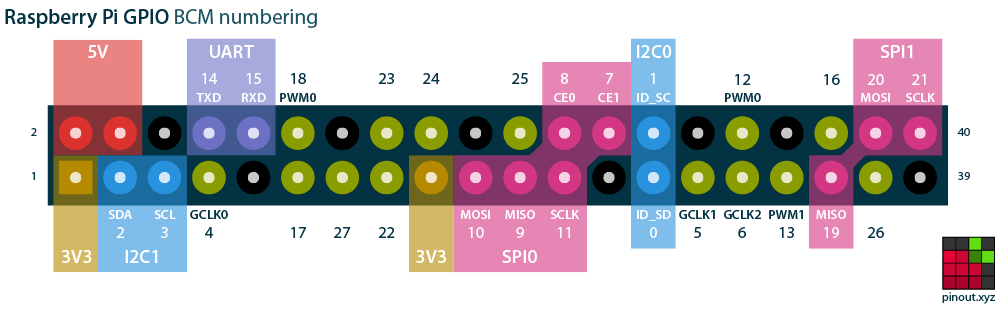 See the Raspberry Pi GPIO Reference and the Interactive Pinout Guide for detailed information about GPIO pins and the interfaces available via the J8 and Blade Hub connectors.
The interractive guide includes pinouts for most third party HATs and pHATs available on the market.
See the Raspberry Pi GPIO Reference and the Interactive Pinout Guide for detailed information about GPIO pins and the interfaces available via the J8 and Blade Hub connectors.
The interractive guide includes pinouts for most third party HATs and pHATs available on the market.
BitScope Blade HUB Signals
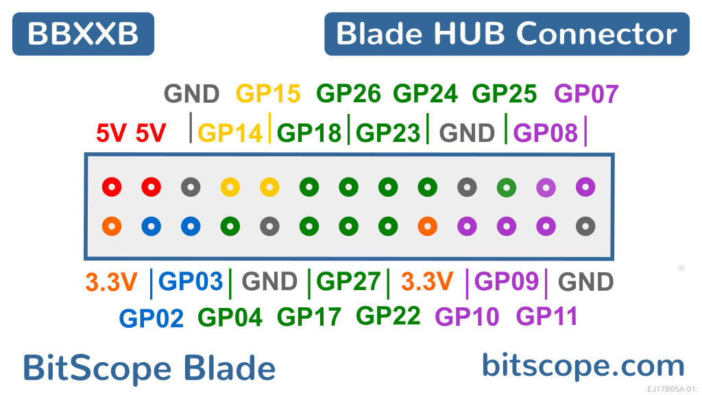
The BitScope Blade HUB Connector makes available a subset of the Raspberry Pi GPIO pins and interfaces including 5V, 3.3V, UART, I2C1, SPI0 and a set of GPIO pins.
GPIO Programming
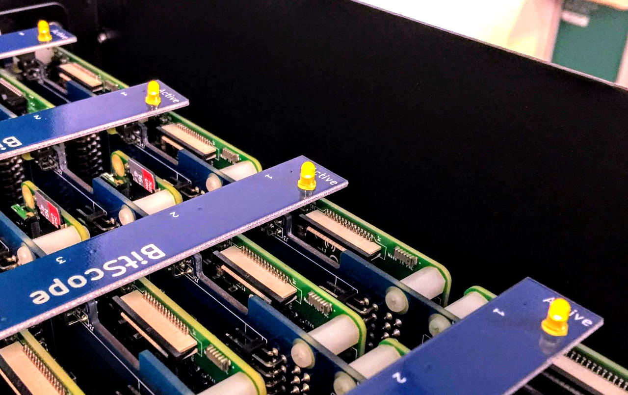
The GPIO Pins are programmable. With one exception, all GPIO are uncommitted and most are available via the HUB connector (underneath each node). GPIO pin 21 is the exception and has a specific purpose; to control the LED underneath each node. This is useful for operational feedback. By default this LED flashes periodically to indicate the node is running normally.
GPIO Shell Guide
GPIO Python Guide
Using Python is very flexible but it requires Python (of course) and a library (to enable access to the GPIO pins). It's very easy to get started using the gpiozero library (documentation).
PXE Network Boot
The Raspberry Pi in the cluster are configured to bootstrap over the network. By default they boot from a DHCP/TFTP/NFS server running on the Cluster Hub which suffices to provide self-test power on operation. It is recommended that a different server be used in production. The default image supplied with the clusters implements a simple server which runs on the SD card or USB drive plugged into the Raspberry Pi 3B+ mounted on the Cluster Hub at the rear of the module.
See the Raspberry Pi Netboot Tutorial for more information.
Purchase Information
| Customer | XXXXXXXXXXXXXXXXXX |
|---|---|
| Purchase Order | ORDER XYZ.pdf |
| Import Declaration | IMPORT DECLARATION.pdf |
| Billing Invoice | BILLING INVOICE XXYYZZP.pdf |
| Shipping Invoice | SHIPPING INVOICE XXYYZZP.pdf |
| Consignment | XXYYXXWW XXXXXXXXXXXX.pdf |
| Shipping Label | FEDEX LABEL XXXXYYYYZZZZWWWW.pdf |
Special Instructions:
Please give the import declaration to your forwarder together with the shipping documents. Your forwarder will need this for customs. Please submit the declaration at the first point of entry. The declaration has to be submitted directly to customs officials.
Shipping Information
| Customer | XXXXXXXXXXXXXXXXXX |
|---|---|
| Supplier | MetaChip Pty. Ltd. |
| office@metachip.com | |
| Phone | M: +61 2 9436 2955 |
| From | Australia |
| To | United States |
| Transport Method | Air Freight |
| Expected Shipment Date | 2019-10-06 |
| Cargo Category | Computer Equipment (FRAGILE) |
| Details of Cargo | Cluster of Raspberry Pi 3B computers |
| packed in 19" rack mount modules. | |
| Shipment Packaging | ISPM15 Certified Export Crate AU-290 |
| Number of Packages | 1 |
| Tracking WayBill | FedEx XXXXXXXXXXXX |
| Package Dimensions (mm) | 565 W x 410 H x 665 L |
| Net Weight (kg) | 18 kg |
| Gross Weight (kg) | 38 kg |
| Volumetric Weight (kg) | 32 kg |
| Product Description | CM60A BitScope Cluster Module |
| Tariff 2018 HTSA Rev 2 | 8471.49.00.00 |
| Net (Product) Value | USD XXXXX / AUD XXXXX / EUR XXXXX |
| Gross Value (Estimate) | USD XXXXX / AUD XXXXX / EUR XXXXX |
Document Revisions
NMEBW9HT |
BitScope Cluster Module User Guide |
|---|---|
| Permalink | https://docs.bitscope.com/NMEBW9HT |
| Document | NMEBW9HT |
| Author | BitScope Designs <sales@bitscope.com> |
| Copyright | © 2019-2020 BitScope Designs |
| License | Attribution-NonCommercial-NoDerivatives 4.0 International (CC BY-NC-ND 4.0) |
| Module ID | XXXXXXXX YY |
| Revision | Update |
| 09 | new design complete |
| 08 | metalwork and power supply changes to accomodate Cluster Blade in progress. |
| 07 | new Cluster Blade prototype tested stand-alone and working. |
| 06 | updated design required accomodated the new blade (for use with Pi 4 Model B) in progress. |
| 05 | updated cooling design has been added this module design. |
| 04 | added a note about using Raspberry Pi 4 with this module design |
| 03 | added hint advising sharing is permitted |
| 02 | typos fixed |
| 01 | created |
| About this Document | This is a Grasp, a single page website. Grasps are responsive, permalinked, documents. They may be read online, emailed, downloaded for offline reading or printed. |