BitScope Cluster Blade
Table of Contents
The Ultimate Raspberry Pi Cluster Solution.
 BitScope Cluster Blade is an industrial solution for building fully managed Raspberry Pi
Clusters. It combines an expandable control plane with programmable BIOS for remote power
management, pre-emptive active cooling, full system monitoring with diagnostics. It offers
geographic addressing and regulated power distribution (up to 50W per board) its
plug-and-play architecture which scales easily from 4 to 96 nodes per module. Multiple
modules combine in racks to create larger clusters.
BitScope Cluster Blade is an industrial solution for building fully managed Raspberry Pi
Clusters. It combines an expandable control plane with programmable BIOS for remote power
management, pre-emptive active cooling, full system monitoring with diagnostics. It offers
geographic addressing and regulated power distribution (up to 50W per board) its
plug-and-play architecture which scales easily from 4 to 96 nodes per module. Multiple
modules combine in racks to create larger clusters.
About Cluster Blade
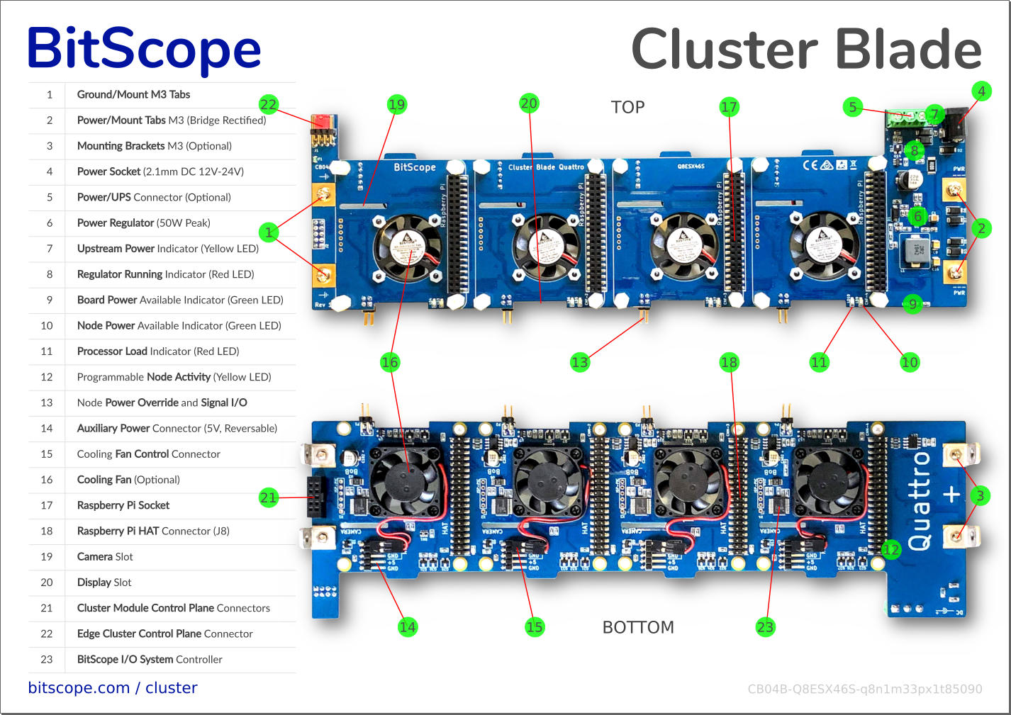
Cluster Blade is BitScope's powerful new cluster building block. A member of the BitScope Blade Family it is a robust power, mounting and control system for Raspberry Pi.

Cluster Blade is backward compatible with the original Blade Quattro but adds full support for Raspberry Pi 4B and Raspberry Pi HAT devices (a two blade ad-hoc cluster shown here).
Cluster Blade Features
Cluster Blade accepts 12V to 28V and regulates it down to a stable 5V at up to 50W (peak). It supports all current Raspberry Pi models (including all 4B variants), offers access to every J8/HAT, 4xUSB and LAN, and up to two HDMI ports per Blade. Cluster Blade includes pre-emptive cooling, voltage, current and power monitoring, remote power control and built-in diagnostic support.
| ✔ Raspberry Pi 4B, 3B+, 3B, 2B or Zero. | ✔ BitScope Cluster Bus & Control Plane. |
| ✔ Accepts 12V~28V unregulated supply. | ✔ Node Power, Bootstrap & Shut-Down. |
| ✔ Provides 5V @ 50W (peak, regulated). | ✔ Power, Voltage & Current Monitoring. |
| ✔ Power Good and Node Load indicators. | ✔ Access USB, Ethernet, HDMI & Audio. |
| ✔ Active Cooling System (Programmable). | ✔ Use stand-alone, in clusters or racks. |
| ✔ Supports Battery Backed UPS. | ✔ Support Raspberry Pi HAT Devices. |
Comparison with Blade Quattro
Cluster Blade (CB04B) appears in the foreground and Blade Quattro (BB04B) behind it. Both are fully compatible with BitScope Blade Racks and Cluster Modules but there are some critical differences. The most significant is full support for Raspberry Pi 4B (all models), more than double the power capacity, integrated cooling and a comprehensive control plane.

BitScope recommends CB04B for all new designs.
Peripheral Connections
All Raspberry Pi USB Ports and LAN Ports are exposed and available.
| Cluster Blade Fully Loaded | CAP Mount SSD Example |
 |
 |
The USB ports (2 x USB3 and 2 x USB2 for each node when using Raspberry Pi 4B) enable the connection of up to four USB devices per node. The most common devices to connect this way are SSD or HDD mass-storage devices. For example, BitScope's 500GB M.2 CAP mount is shown here.
Cluster Blade provides up to 500mA per USB Port (per Raspberry Pi specs) across all four ports on every node subject to the 50W blade power budget. The HDMI ports, USB-C and Sound Port for node 1 are also accessible enabling this Raspberry Pi to be used as a desktop workstation (the other three being a headless "private cloud").
The Raspberry Pi Camera and Display connectors are accessible (on the HAT side of the blade) allowing the use of up to 4 Raspberry Pi compatible cameras and display devices.
Expansion Hardware
Cluster Blade makes the Raspberry Pi HAT (J8) connector available to every node.
For example, shown here mounted with the Raspberry Pi on the underside, the HAT bays are populated with four different type of HAT devices:

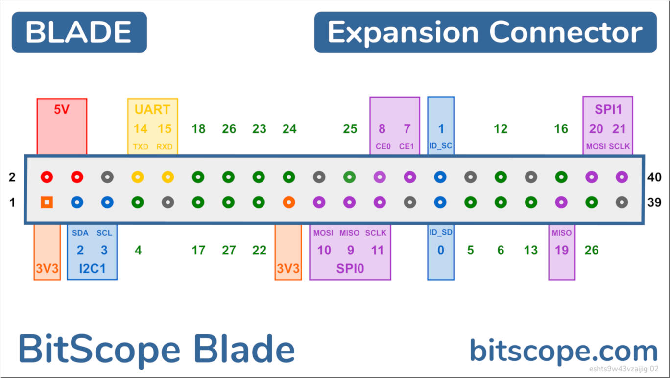
J8 Connector
All J8 signals, power and ground are available to connected HAT devices.
Of these, three may also be used by Cluster Blade itself (depends on configuration):
| PIN | GPIO | Fn | Description |
|---|---|---|---|
| 8 | 14 | UART TXD | BMC Transmit Channel |
| 10 | 15 | UART RXD | BMC Receive Channel |
| 40 | 21 | SPI1 SCLK | Blade Activity LED |
Each BMC is accessed by the Raspberry Pi it manages via the Pi's primary serial port. This serial port appears on GPIO 14 & 15 but is also (internally) connected so you don't need to connect anything to these pins to access the BMC. By default, the BMC is locked. It must be unlocked before use. This ensures that any connected HAT device that also uses the serial port can be used without interference from the BMC. In this case, the BMC should only be accessed via the control plane.
The BitScope Blade Activity signal drives the node activity LED. The use of this LED is optional. If the SPI1 peripheral is used by a connected HAT it may be ignored.
Product Assembly Guide
Cluster Blade is supplied with fans and mounting components (Raspberry Pi are sold separately).

Assembly is quick and easy:
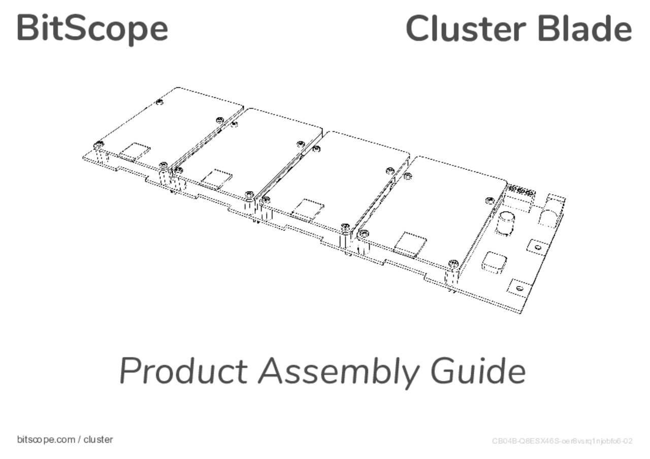
See the Quick Start Guide for more information.
Cluster Management
In addition to the power and mounting features of the original BitScope Blade Quattro, this new Blade includes a Cluster Control Plane which communicates via a dedicated Control Bus. This frees the primary network from a cluster management role and facilitates functionality not possible via the network (e.g. power and run-time control, crash recovery and diagnostics etc).
The Control Plane is part of the BitScope I/O System (built into the Cluster Blade) and it can be extended across an entire cluster. It operates completely independently of the cluster nodes. No software is required to run on the nodes to use it. The API supports dynamic and interractive operation (via a serial terminal) to ease cluster commissioning. It is fully script programmable requiring no dedicated drivers for when the cluster is in production use.
Cluster Control Plane
A control plane is a sub-system of a cluster that allows a cluster manager (an external computer or one of the cluster nodes) to (remotely) manage operation of the nodes in the cluster. Usually, it manages the cluster power and cooling sub-systems. Cluster Blade does this via the BMC.
The control plane also provides out-of-band communications channels which can be used to manage and share data and system control between the cluster manager and the cluster nodes. This can be used to implement graceful power-down, error recovery, remote console logging, debugging and even out-of-band networking (e.g. in the event of primary network failure).
Cluster Types
Two types of BitScope Cluster can be built with Cluster Blade:
| TYPE | DESCRIPTION |
|---|---|
| Managed | Uses an External Cluster Manager and takes control of the cluster hardware (power, cooling, control etc). Nodes may still monitor their own slot in the cluster (power, temperature etc) but they cannot control it nor communicate with other nodes via the control plane. This type of cluster is recommended in applications where nodes may not be trusted (e.g. hosting infrastructure) or where cluster management needs to be centralised or delegated to an external system. |
| Unmanaged | Has no external cluster manager. Any node may become the cluster manager. There is no need for an external cluster manager. Each Node may access and control its own slot in the cluster. Not secure at the hardware layer (by default) but can be configured to become secure (similar to a managed cluster). Nodes may talk to each other directly (via the control plane, acting as a low bandwidth out-of-band network). Well suited for smaller edge/ad-hoc and single purpose clusters. |
In both cases, Cluster Blade supports the serial console (on each node) and includes hardware layer access control for cluster deployments in untrusted environments such as cloud infrastructure.
Managed Cluster
Uses an external cluster manager. The cluster manager has full access to any node's hardware. Each node has monitor access to its own hardware.
			 ----
/<===================|T   |
|                    | PI | MASTER
|  /================>|R   |
|  |                 ----
|  | RS485
|  |
|  |  B          A
|  |      -----       ----
|--|---->|R   R|<----|T   |
|  |     | BMC |     | PI | NODE 0
|  |<----|T   T|---->|R   |
|  |      -----       ----
|  |
|  |      -----       ----
|--|---->|R   R|<----|T   |
|  |     | BMC |     | PI | NODE 1
|  |<----|R   T|---->|R   |
|  |      -----       ----
|  |
|  |      -----       ----
|==|====>|R   R|<====|T   |
|  |     | BMC |     | PI | NODE 2 SLAVE
|  |<====|T   T|====>|R   |
|  |      -----       ----
|  |
:  :      ::::       ::::
|  |
|  |      -----       ----
\--|---->|R   R|<----|T   |
   |     | BMC |     | PI | NODE 96
   \<----|T   T|---->|R   |
	  -----       ----
Unmanaged Cluster
Unmanaged cluster where any node can become the cluster manager (master) with full access to any other node hardware (slaves). Each node retains full access to its own hardware.
	  B          A
              -----       ----
/=======>|R   R|<====|T   |
|        | BMC |     | PI | NODE 0 MASTER
|<=======|T   T|====>|R   |
|         -----       ----
|
|         -----       ----
|------->|R   R|<----|T   |
|        | BMC |     | PI | NODE 1
|<-------|R   T|---->|R   |
|         -----       ----
|
|         -----       ----
|=======>|R   R|<====|T   |
|        | BMC |     | PI | NODE 2 SLAVE
|<=======|T   T|====>|R   |
|         -----       ----
|
:         ::::        ::::
|
|         -----       ----
|------->|R   R|<----|T   |
|        | BMC |     | PI | NODE 96
\<-------|T   T|---->|R   |
              -----       ----
Cluster Control Bus
The Control Plane communicates via a built-in Control Bus. The bus interconnects all four nodes on the Blade board via differential serial bus (RS-485). The bus has extension connectors to enable multiple Blades to be interconnected to create Cluster Modules comprising up to 24 blades.
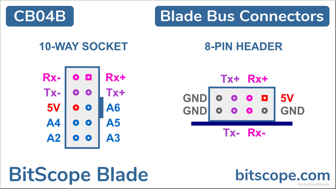
There are two connectors.
- The 8-way Ad-Hoc Cluster Connector is typically used to create ad-hoc clusters where the node addresses are manually configured and stored in configuration memory of each board. In stand-alone operation the 8-way connector has shorting headers (in red) which connect Tx and Rx signals. This allows any node to become the cluster master and is required for unmanaged cluster operation.
- The 10-way Cluster Module Connector is used to interconnect Blades in Cluster Packs. It includes geographical address lines to generate physical address of the nodes on each board.
The connectors are located at the rear (Ad-Hoc) of the blade and at the left edge (Module). Connection is made via twisted pair or ribbon cable in the case of the Ad-Hoc Connector or is "built-in" when mounted in Cluster Packs in the case of the Module Connector.
| 8-way Ad-Hoc Cluster Connector | 10-Way Cluster Module Connector |
 |
 |
| Cluster Pack Bus Connection | Cluster Pack Address Switch |
 |
 |
When mounted in Cluster Packs, the address of each pack is assigned via switches on the Cluster Plate. Multiple Cluster Packs (at different addresses) are then inter-connected using ribbon cables (connected "daisy chain" via the pair of 10-way sockets on the end plate).
BitScope I/O System (BIOS)
The BitScope I/O System is used to control the operation of Cluster Blade nodes.
It does this via an embedded network of baseboard management controllers (BMC).
The BIOS provides access to all BMC, both locally and remotely via a Control Bus. A Universal Unique Identifier (UUID) identifies each node globally. A Geographic Address is used to address each node in a single cluster.
Baseboard Management Controller (BMC)
A baseboard management controller is a specialised service processor that monitors the state and controls the operation of each compute node (i.e. each Raspberry Pi). There is one BMC per node in Cluster Blade. All BMC are connected via an out-of-band control bus. The BMC runs a sub-set of the BitScope Virtual Machine. The VM implements the Cluster Blade BIOS. It has a set of byte-wide registers and single byte commands that provides for the real-time monitoring of key system values including supply voltage and current as well as node current, temperature, fan speed, processor state and more.
The term BMC derives from the superseded Intelligent Platform Management Interface (IPMI) specification, developed by Intel and used by hundreds of computer vendors. Important: while BMC in Cluster Blade functionally similar to IPMI or OpenBMC its implementation is different.
BIOS Modules
The features of the BIOS are provided via a set of modules.
They are accessed and executed via one or more commands acting on zero or more registers.
The commands and registers used depend on which module is being used.
The modules implemented in Cluster Blade (Revision CB04A016) are:
| MODULE | DESCRIPTION |
|---|---|
STATUS |
Machine Status. Used to report the machine status including power state, current draw and fan speed. The cluster manager uses this to provide real-time reporting of the status of the cluster at the hardware level. |
POWER |
Power Controller. Used by the cluster manager (master) to control the power of each cluster node (slave). Includes power-on/bootstrap and shut-down/power-off. |
METER |
System Monitor Read a system monitor channel to return its value. There are multiple channels including the raw voltage, current and node current/power, ground and Vcc reference voltages and temperature. |
FAN |
Cooling Control Read and/or Update FAN Control parameters. These allow the minimum (idle cooling), maximum (noise abatement) and speed control parameters. |
CONSOLE |
System Console Provides remote access via the control bus to each node's system console, bootloader, firmware, kernel and operating environment. |
MAILBOX |
Token Exchange. Used to implement power control protocols, between the cluster manager and a cluster node. |
SRAM |
Shared Memory. Use is application specific. For example it may be used to implement an out-of-band IP network or in support for cluster orchestration. |
EEPROM |
Persistent Memory. Used for Device Configuration and Boot-Time program execution. Factory defaults establish the blade to be used stand-alone or as part of an unmanaged. Modified values may be used to configure for managed cluster operation or change defaults for different types of work-load. |
CAL |
CAL Memory Machine Calibration Coefficients used to calibrate various monitor measurement. |
Configuration
The configuration defines
how the cluster operates
at boot time
and how it continues to operate
in the event that it
receives no communications
from the host or
(via the control plane)
from the cluster manager.
Any configuration parameter
that has a value ff is
unconfigured and ignored.
If a parameter has a different value
it will be used at boot time to
modify the operation of the BMC.
| PARAMETER |
|---|
Power Off. When assigned a value 55, the node will boot with the power disabled. Note: it is not possible to have default master (address 7c) to boot with power disabled (to do so would risk losing control of the blade on which the node is located if all the other nodes were also powered off at boot). |
Address Override. When assigned, its value will be used to set the node address in the cluster at boot time if the blade is stand-alone or in an ad-hoc cluster. Legal values range from 00 to 7f. If the blade is located in a BitScope Cluster the physical address of the blade in the cluster will override this. |
Fan Scale. Overrides the factory default value of the SCALE parameter in FAN Control. |
Fan Limit. Overrides the factory default value of the LIMIT parameter in FAN Control. |
Fan Offset. Overrides the factory default value of the OFFSET parameter in FAN Control. |
No Fan. When assigned aa, upon the next boot, the node may no longer change the fan control parameters. The master may still modify the Fan paramters. |
No SRAM. When assigned aa, upon the next boot, the node may no longer access SRAM. The master may still use SRAM (normally for hardware system logging which cannot be modified or updated by the node. |
Peon. When assigned aa, upon the next boot, the node will become a strict slave if the blade is part of BitScope Cluster. It cannot become master and it cannot change its own configuration parameters. Peon is ignored on a stand-alone blade or an ad-hoc cluster. |
Peon Mode
A node may be Peon
which means it does not have permission
to become a cluster manager (Master) or
to change its own configuration.
This will be the case
in a managed cluster by default
because configuration
is the exclusive domain
of the cluster manager.
Asserting Peon Mode in an unmanaged cluster achieves the same result.
A node can always read its own configuration
so it can know how it has been set up to run.
To disable Peon, No SRAM and/or No Fan
the master must change parameter value
to something other than aa.
Power Connections
Cluster Blade provides connectors for unregulated power input (at 12V to 28V), trickle charge and UPS backup (with an SLA battery), regulated power output (at 5V), variable cooling fan power (at 5V) and manual node power overrride.
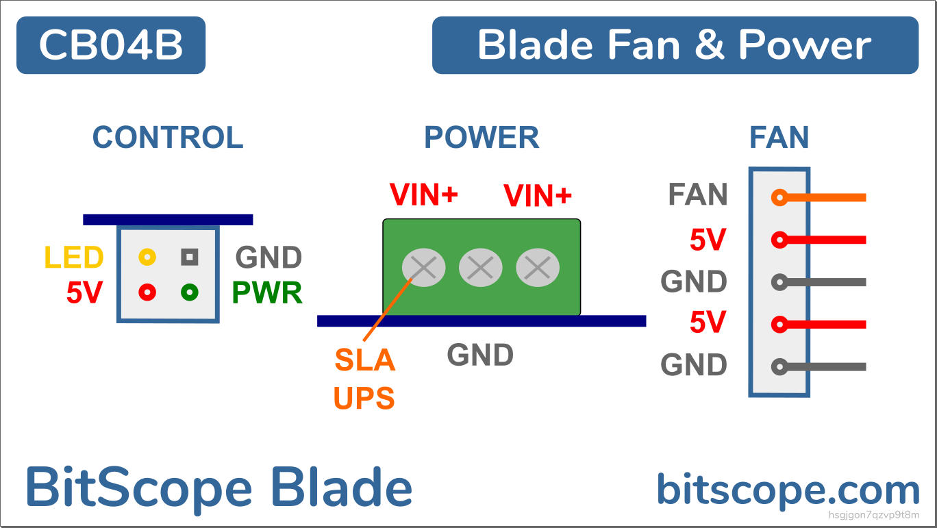
Which of these is used depends on physical deployment. When used stand-alone the connectors available are the 2.1mm socket and 3-way screw terminal block. The other alternative is to connect power via the mounting tabs at the edge of the board when used with Cluster Packs.
| 2.1mm and 3-way Terminal Block | Power and Mounting Tabs |
 |
 |
All connection methods are diode protected ensuring power cannot be applied the wrong way around. The 2.1mm socket (Center Positive) is intended for desktop or single blade rack use. The terminal block is intended for stand-alone industrial deployment. It has two VIN+ connections; power supply input and (optional) SLA battery input/output. The connection in the middle is the power supply ground (optional if the chassis is ground connected). It is also possible to power the Blade via the 2.1mm socket and connect an SLA battery for UPS via the terminal block.
When power is connected via the mounting tabs, VIN+ is applied to one of them and GND to the other. The polarity does not matter (the input is bridge rectified). When connected as part of a cluster pack, power is supplied via cluster plate to which it's connected.
| Cluster Pack Tab Connected Power | ATX Compatible Cluster Pack Power Sockets |
 |
 |
Power is applied to the entire pack via one of the ATX Compatible connectors on the cluster plate. ATX connectors enable the use of industry standard power supplies to power Cluster Packs and Blade Racks and Cluster Modules built from them.
Power and Cooling
Providing sufficient power and extracting heat unavoidably generated are critically important when running compute clusters. Cluster Blade is designed to do this under conditions of heavy load in sometimes adverse environments. It accepts 12V to 28V and regulates it down to a stable 5V at up to 50W (peak). This is more than enough for the heaviest of work-loads.
Power Requirement
Power and Raspberry Pi can be a confusing topic. You need to consider:
- Power-on current draw (which can be very large),
- Idle and power-down power load,
- Heavy-load and/or overclocked power and
- Cooling required to disspate the heat.
The BitScope Blade family (including Cluster Blade) is unique (in the world of Raspberry Pi Power solutions) because it accepts an unregulated source and regulates it to 5V locally to the Raspberry Pi. It provides power via the J8 connector and not via the Micro USB or USB-C. It also has very high peak power capacity so the power adapter problems that plague some third-party solutions do not arise. It also means that over-specifying the power source (to meet the power-on current draw while avoiding supply voltage drop at power-on) is not required.
Cluster Blade itself needs up to 15W (for diode and regulator drops, cooling fans, BIOS and Control Plane). With another 50W available for the four Raspberry Pi and any peripherals, a power source capable of delivering about 70W (per Blade) will work. For example, 12V@6A or 24V@3A.
Cluster Blade Power Tests
The early Raspberry Pi (based on Broadcom BCM2835) were very low power (typically around 2W). They generated very little heat but they only ran at about 900MHz and had few on-board resources. The new Raspberry Pi Model 4B (using Broadcom BCM2711) is a beast in comparison. It executes at 1.5GHz with Gigabit Ethernet, USB-3 and up to 8G of RAM. The Raspberry Pi engineers have worked miracles to do this but it can still consume a lot more power (~10W when overclocked and under load) and can generate quite a bit more heat.
This is the prototype in testing with 4 x Pi4B 4G running overclocked to 2GHz executing the heaviest workload we could manage:

The total power draw in this case was 48W. This test was conducted over a weekend. The fans ran at full speed and all Raspberry Pi 4G stabilised between 69°C and 72°C (well below the governor limit) in a test room with an ambient temperature between 22°C and 25°C (the aircon was off). This was running early firmware. Raspberry Pi consumes about 10% less power now.
Bottom line: Cluster Blade provides the necessary power and extracts the generated heat.
Active Cooling System
Cluster Blade includes active cooling using pre-emptive load monitoring to manage cooling fans which are located directly above the CPU on each node. Cooling fan operation is managed by the Blade itself (it does not require the node to do anything). Auxiliary 5V power is also available (via the 5-pin connector) and power override is available via the 4-pin header at each node.
Fan control is automatic and operates by measuring the node current draw to calculate the fan speed required to pre-emptively dissipate the heat generated. This relies on a heat profile.

The fan control algorithm has profile parameters (accessible via the BIOS) that allow the node to increase or decrease the flow as required. For example, if the cluster is running heavy work-loads or the ambient temperature in deployment is high, the fan control can be increased. When used in a low load or cooler environment fan speed can be pulled back to reduce airflow and fan noise.
The default settings apply without intervention by the node. They scale the fan to operate from idle to full flow based on the heat profile of Raspberry Pi Model 4B. The configuration setting can be adjusted to override these detaults for a different node type or use case. Alternatively, the node can monitor and directly manage its own cooling settings (for example, if deploying an algorithm that uses the node's own temperature sensing hardware).
Is this fan not spinning because it's broken?
Probably not.
Whether a fan spins and how fast depends on the workload of the node. The workload (and therefore, heat generated) depends on node current. The Active Cooling System measures the current and applies a heat profile to determine the power to apply to the fan. How fast the fan spins in response, especially at the low end of the range, depends on mechanical characteristics of the fan. Some fans are a little more sensitive than others. With the factory defaults, some fans may not spin at all when a node idles. This is normal and does not affect the operation of effectiveness of the cooling system.
However, if you are concerned a fan is not spinning because it is broken, you can check:
| Active Control, Fan Stopped | Manual Control, Fan Spinning |
 |
 |
Connect power as shown in the manual control example (on the right). This applies 5V directly to the fan. If the fan is working, it will spin at full speed regardless of the active control system. If it fails to spin, it is probably broken and should be replaced. Important: the active control system is fully configurable. If using a different Raspberry Pi, or peripherals that generate more heat, the heat profile may be changed to suit, using the fan control configuration parameters.
Node Power Management
Node power is normally controlled via the control plane.
The / and \ BIOS commands are available to do this.
These commands are ignored if a node sends them to itself.
They are only useful to manage power on a slave node when issued from a master (via the control plane).
| CMD | COMMAND | MEANING |
|---|---|---|
/ |
POWERON | Turn power on (starts node) |
\ |
POWEROFF | Turn power off (hard stop) |
The Power Commands reply a state token:
| TOK | STATE | MEANING |
|---|---|---|
0 |
OFF | Power is OFF (host may be disabled or unavailable, unknowable) |
1 |
ENABLED | Power is ON and host is available and powered has been applied |
2 |
DISABLED | Power in ON but power has been manually disabled |
Note that this is a hard power down. If the slave node being powered off needs to perform housekeeping before power is removed, it's up to higher layer procotols (used to manage the cluster) to ensure this happens. If the nodes do not have other means to communicate (i.e. the LAN) the control plane mailbox is availble to implement protocols to do this. For example, to implement a management protocol analogous to UNIX Init, a set of master "mailbox tokens" are defined:
| TOK | COMMAND | MEANING |
|---|---|---|
0 |
HALT | Halt (shut down gracefully) |
1 |
SYSTEM | Boot into Single User Mode. |
2 |
RUNLEVEL2 | Boot to runlevel 2. |
3 |
RUNLEVEL3 | Boot to runlevel 3. |
4 |
RUNLEVEL4 | Boot to runlevel 4. |
5 |
RUNLEVEL5 | Boot to runlevel 5. |
6 |
REBOOT | Reboot. |
10 |
STATUS | Report current status. |
These would be issued by the cluster manager (master) and received by the node (slave). A set of matching slave state tokens are defined as:
| TOK | STATE | MEANING |
|---|---|---|
0 |
OFF | Power is OFF (host may be disabled or unavailable, unknowable) |
1 |
ENABLED | Power is ON and host is available and powered has been applied (nothing else is known) |
2 |
DISABLED | Power in ON but host is disabled or host is unavailable |
3 |
STOPPING | Power is ON and one (or more) request(s) to power down have been received |
4 |
STOPPED | Power is ON and the host has acknowledged the power down |
5 |
RUNNING | Power is ON and host has reported it's running (more detail as yet unknown) |
6 |
ERROR | Error or unknown state. |
11 |
SYSTEM | Single User Mode. |
12 |
RUNLEVEL2 | Runlevel 2. |
13 |
RUNLEVEL3 | Runlevel 3. |
14 |
RUNLEVEL4 | Runlevel 4. |
15 |
RUNLEVEL5 | Runlevel 5. |
The master can issue STATUS at any time to ask the slave for its state.
When STOPPED the master knows it is safe to POWEROFF of the node.
If the state never reaches STOPPED (either because the host has crashed or the host is not running software to report this to the BMC) after a (master defined) timeout, the master can POWEROFF the node.
Node Power Override
By default power is applied to all nodes when power is applied to the Blade. This may be overridden by connecting a header across the lower pair of pins on the 4-pin header underneath each node.

This allows the Blade to be used without the need to activate or use the control plane and is intended as a mechanism to clamp a node from powering on regardless of the control plane. It's useful when installing or commissioning or when the cluster control plane is not being used.
Raspberry Pi Clusters
BitScope Cluster Blade is designed for building industrial quality Raspberry Pi Clusters. The design distills years of experience creating Raspberry Pi clusters from small to very large for a wide range of commercial, industrial and educational applications.
A bit history may help explain where Cluster Blade came from and why it is designed the way it is.
Raspberry Pi Clusters have been around almost as long as Raspberry Pi itself.
However, they came of age in 2017 when BitScope built the first large industrial cluster (comprising 3000 cores) for Los Alamos National Laboratories. This original design was constructed using BitScope Blade and Raspberry Pi Model 3B. While not particularly powerful (for typical cluster computing applications) there was a clear purpose for its construction:
These modules were very large and somewhat unwieldy. After Los Alamos many other applications emerged, typically in research and educational applications. We manufactured and shipped these modules both fully built, and as flat pack products:
CM144A 144 Node Cluster Module |
Cluster Module Flat Pack |
 |
 |
This original did not have a control plane so in 2018 BitScope developed BitBar, a control plane for Pi Clusters which was retrofited to the original design.

BitScope's core cluster module design has been refined and used to build fully functioning remotely managed clusters ever since.
After seeing the original large design many customers sought smaller modular solutions so we developed CM48A a 48 node module.
It is a turn-key solution combines network fabric, control plane and cooling system in single half-depth rack unit.
At the rear is a cluster controller and power supply sub-system:
CB48A 48 Node Cluster Module |
Cluster Controller and Power Supply |
 |
 |
With Cluster Blade we have distilled the essence of this entire design into a single plug-and-play product. Clusters built with Cluster Blade are more compact and far more powerful. They scale from 4 nodes to 96 mode per module and work with all Blade Rack products. Cluster Blade embeds comprehensive cluster control, cooling and orchestration on the board. It includes BitScope's sophisticated test, measurement and data acquisition technologies to enable real-time cluster voltage, current, power and temperature monitoring.
BitScope Micro Cluster
The smallest cluster is a single blade, stand-alone, in a desktop enclosure or a 1U rack:
CM04A BitScope Micro Cluster |
 |
| Stand-Alone Blade | Single Blade Desktop |
|
 |
Cluster Packs
The smallest multi-blade cluster is a Cluster Pack:
| Cluster Packs |
 |
A Cluster Pack comprises 2, 3 or 6 Cluster Blades and a pair of Cluster Plates that integrate mounting, power and cluster control without any internal wiring. Some are designed for use in racks, others for use in cluster modules. They can be mixed and matched in to create custom clusters because all of them use the same integrated power distribution and control plane. A dedicated cluster controller and power distribution sub-system is no longer required and active cooling, temperature and power monitoring is integrated into each blade.
Edge Racks
Small clusters can be built with Edge Racks:
ER08A 8 Node Edge Rack |
ER12A 12 Node Edge Rack |
 |
 |
ER24A 24 Node Edge Rack |
ER48A 48 Node Edge Rack |
 |
 |
Cluster Packs are mounted in rack units. A variety of options for different applications are available.
Cluster Modules
The largest clusters are built as Cluster Modules:
| 48-Node Cluster Module | 576-Node Pi Cluster |
 |
 |
Cluster Packs are combined in rack units to make Cluster Modules.
Technical Specifications

| Compatibility | Raspberry Pi 4B, 3B+, 3B & 2B Any Raspberry Pi that conforms to the HAT specification is compatible. |
| Nodes per Blade | 4 Number of Raspberry Pi node that may be connected at the same time. |
| Total Power Budget | 50W (9A continuous 10A peak) Peak and continous current available at 5V across all slots and connected peripheral devices. |
| USB Ports | 8 x USB3 + 8 x USB2 (Pi 4B) Refers to the number of USB and Network ports (provided by connected Raspberry Pi). |
| Network Ports | 4 Number of simultaneous network connections. Specifes the number of ports required of an externally connected network switch to make full use of the product. |
| USB I/O Bandwidth | 44 GBit (4B) Combined USB I/O bandwidth across all nodes assuming the most up-to-date model Raspberry Pi supported by the product is used. |
| Internal Network Bandwidth | 4 GBit (4B) Combined internal network bandwidth calculated as the sum total effective bandwidth all node assuming the most up-to-date model Raspberry Pi supported by the product is used. |
| HDMI Outputs | 2 (Pi4B) or 1 HDMI and Audio ports on the Raspberry Pi in Slot 1 are accessible for connection. |
| HDD/SSD Support | ✔ M.2 and/or external USB3 connected HDD and SSD supported with up to 500mA available per connected drive. |
| Max HAT Devices | 4 Number of connectable Raspberry Pi compatible HAT devices (subject to power budget). |
| Max CAP Devices | 4 Number of BitScope CAP (USB connected), per Blade (subject to power budget) |
| Active Cooling System | ✔ Provides mounting and control for 30mm cooling fans (per node) with programmable control. |
| Built-in Control Plane | ✔ Built-in control bus for full control plane functionality on-board. |
| BitScope I/O System API | ✔ Uses the BitScope Input/Output System (BIOS) API (an ASCII based script programmable VM). |
| Geographic Node Addressing | ✔ Default node address is built into the Blade (no configuration required). |
| Voltage, Current & Power Monitor | ✔ Built-in BitScope Measurement functions for supply voltage, board and node current and power. |
| Manual Node Power Control | ✔ Each slot may be individually powered up/down via this header (normally powered up). |
| Cluster Module Control Bus | ✔ RS-485 Control Plane connector with geographic addressing for Large Cluster construction. |
| Node UUID, SRAM & FLASH | ✔ Built-in UUID per node with off-node SRAM and FLASH programmable configuration memory. |
| Message Passing System | ✔ Mailbox based out-of-band synchronisation and message passing system for node control. |
| Remote Doagnostics Support | ✔ Support for access to serial terminal based diagnostics on each node in managed clusters. |
| Single Egde Power Tabs | ✔ The blade may be powered via the mounting tabs, eliminates power wiring when rack mounted. |
| Reversable Power Inputs | ✔ Supports either polarity for tab connected power when building ad-hoc clusters. |
| Redundant Power Support | ✔ Supports the use of dual (redundant) power supplies with bridge rectified failover and continous operation. |
| Soft-Knee Power Control | ✔ Control bus power-on enable is "soft turn-on" ensuring reliable cross-cluster power management. |
| Short Circuit Protection | ✔ A short-circuit produces graceful board level shut-down not overheating or board failure. |
| SLA/UPS Support | ✔ Blocking diode enables use with UPS and battery backup power solutions. |
| Camera Slots | ✔ Camera slots to enable the connection of visible or IR cameras. |
| HAT/Primary Power | 5V via J8 Primary power for connected Raspberry Pi and HAT devices. |
| Auxilliary Power | 4 x 5V Auxilliary power for devices connected via 3-pin power headers (e.g. Raspberry Pi Display) |
| Indicator LEDs | Power, Load & Signal LEDs to indicate BAY reset and interrupt inputs. |
| Processor reset/interrupt | ✔ The device in each slot may be individually reset or interrupted via this header. |
| SPI, I2C, Serial & GPIO | ✔ Access to each Raspberry Pi GPIO, SPI, I2C and Serial signals. |
| BitBar Control Plane | ✔ Compatible with BitBar External Cluster Control plane technologies. |
| Diode Protected Power | ✔ Protection from the application of source power with the wrong polarity. |
| PoE Compatible DC 2.1mm | ✔ DC 2.1mm power socket compatible with low cost passive PoE solutions. |
| Power Requirement | 12V (6A) ~ 28V (2.5A Input power requirement. This is usually greater than the regulated power provided by the product to power the nodes and takes account of the additional power required to run the other sub-systems of the product.) |
| Operating Temperature | 0 °C to 70 °C Nominal environmental operating temperature to safely use the product. Performance may be degraded is used outside normal equipment operating conditions. |
| Storage Requirements | -40 °C ~ +40 °C, 5 % ~ 95 % RH Nominal environmental storage temperature to safely store the product. |
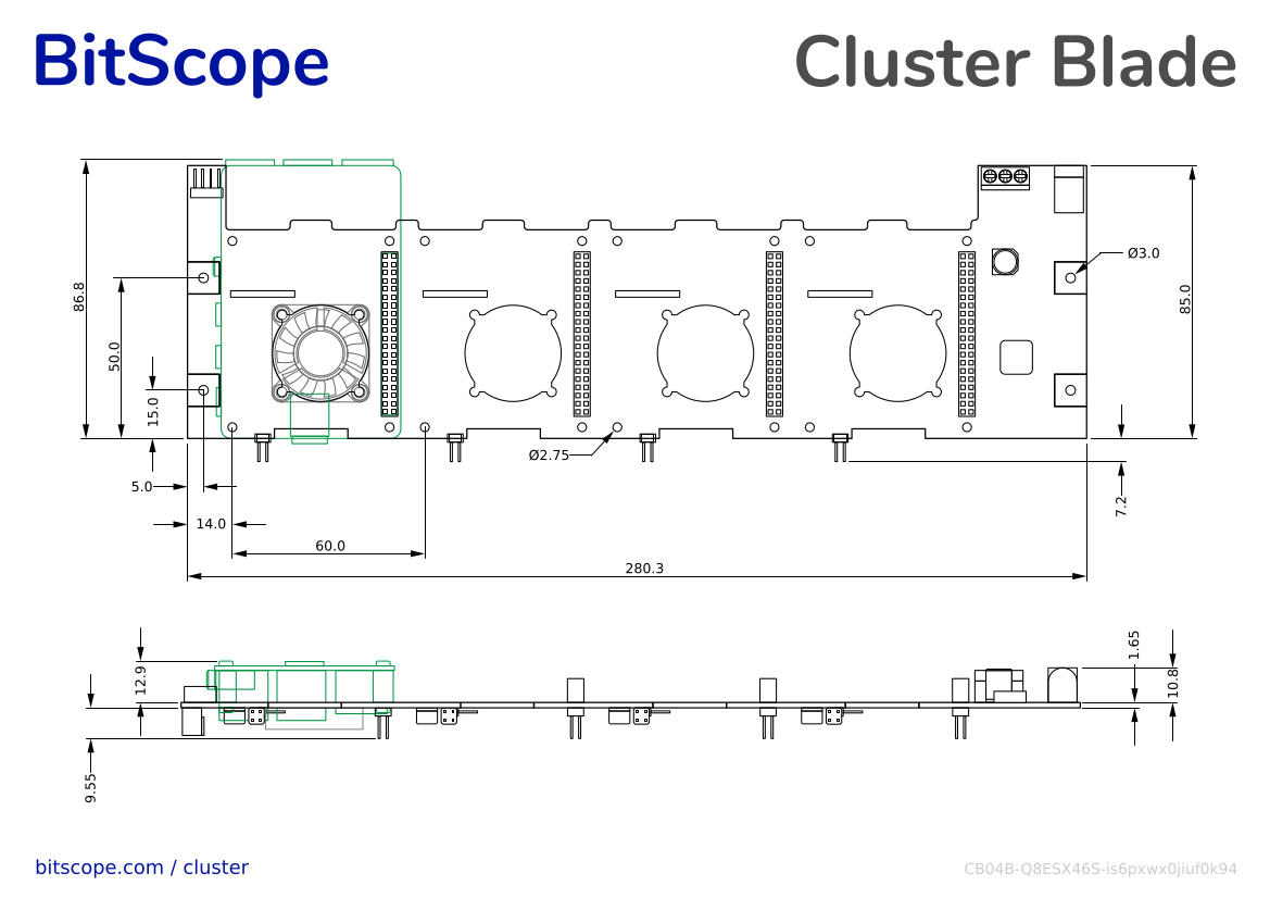
| Dimensions (W x D x H) | 85 x 280 x 23 mm Product external dimensions in normal use. |
| Weight (PCBA, Loaded) | 150g, 350g Net weight of the product with no optional accessories installed. |
Order Online
You may buy Cluster Blade direct from BitScope. This is a new product and orders will be processed in the order they're received. If you want to rack mount a Cluster Blade have a look at BitScope Micro Cluster. If you want to build larger clusters with Cluster Blade have a look at this example. Let us know your requirements - we have many custom options available.
| BitScope Cluster Blade | Order Online |
 |
 |
Impressum
(about this website)
CBGHYESM |
BitScope Cluster Blade |
|---|---|
| Link | docs.bitscope.com/cluster-blade |
| Author | BitScope Products <products@bitscope.com> |
| Copyright | © 2021-2023 MetaChip Pty. Ltd. T/A BitScope Designs |
| License | Attribution-NonCommercial-NoDerivatives 4.0 International (CC BY-NC-ND 4.0) |
| Feedback | We welcome your feedback. If you find any errors, omissions or just information that is confusing or incorrect, please email us at feedback@bitscope.com with details. |
| Date | |
| Rev | hfqegj24qm8l0wg5 |
| Purchase | https://bitscope.com/buy/CB04B |
| Enquiries | BitScope Sales <sales@bitscope.com> |